
Optical crossconnect device and monitoring method of optical crossconnect device

a monitoring method and cross-conect technology, applied in the direction of optical elements, electromagnetic repeaters, instruments, etc., can solve the problems of ineffective function, large influence of cross-conect devices on users utilizing optical cross-conect devices, and inability to optimize switching conditions by this patent document, etc., to achieve high stability and reliable

Active Publication Date: 2006-10-10
FUJITSU LTD
View PDF4 Cites 0 Cited by
  • Summary
  • Abstract
  • Description
  • Claims
  • Application Information

AI Technical Summary

Benefits of technology

[0016]The present invention has been proposed considering the problems described above and it is therefore an object of the present invention to provide an optical crossconnect device of higher stability and reliability which can always verify the operations of an optical switch forming the optical crossconnect device and a monitoring method of the optical crossconnect device.
[0024]The optical crossconnect device according to the invention wherein the multiplexing means for multiplexing optical signals in unit of wavelength to output optical signal in unit of waveform group and the monitoring signal generating means for generating the monitoring signal for monitoring the optical switch circuit of the waveform different from that of the input optical signal supplied to the optical transmission signal input portion of the relevant optical crossconnect device are comprised, and since the multiplexing means is always capable of supplying the optical signal to the optical switch circuit without relation to the optical signal input condition from the external side by multiplexing the optical signal of the monitoring signal generated by the monitoring signal generating means and the optical signals in unit of wavelength supplied to the optical transmission signal input portion and then supplying the multiplexed optical signal of wavelength group to the optical switch circuit, the normal condition of the optical switch can always be monitored and optimized operation of the optical switch can always be performed and thereby stability and reliability of the optical switch can be improved.
[0025]Moreover, since the optical signal can always be supplied to the optical switch circuit by multiplexing the monitoring signal of the wavelength different from that of the external input optical signal to the external input optical signal, input switching process of the external input optical signal and the monitoring signal is no longer required.
[0030]According to the invention, it is possible to provide the highly stable and reliable monitoring method of the optical crossconnect device which is always capable of realizing the verification of operations of the optical switch forming the optical crossconnect device by supplying the monitoring signal for monitoring the optical switch circuit to this optical switch circuit in unit of wavelength, wavelength group or optical fiber when the optical level of the optical signal in unit of wavelength, wavelength group or optical fiber supplied to the optical transmission signal input portion of the relevant optical crossconnect device is the predetermined level or less.

Problems solved by technology

However, since the optical crossconnect device accommodates traffics of large capacity, a failure of the optical crossconnect device will give large influence to users utilizing the optical crossconnect device.
However, the invention described in the patent document 1 has a problem that the function does not become effective if the reference optical signal is not received.
Moreover, the switching condition cannot be optimized by this patent document.
However, when the optical signal inputted from the external side disappears, the optimizing operation is stopped.
As a result, here rises a problem that verification of normal operation of the optical switch becomes difficult and the stable output cannot be assured when the optical signal is inputted again.
Moreover, when the normal operation is verified by comparing optical intensity of the input optical signal and output optical signal of the optical switch circuit, it is difficult, unlike the signal of electrical level, to verify normal condition only by setting the path in the device.
Therefore, it cannot be verify before start of the operation by user that optical switch circuit in relation to the relevant user is surely functioned and therefore failure of the device can be determined after the optical signal of user is actually inputted.
For this reason, the failure can be detected initially in some cases after the user signal starts the operation, resulting in the problem that reliability is rather low.

Method used


Image

  • Optical crossconnect device and monitoring method of optical crossconnect device
  • Optical crossconnect device and monitoring method of optical crossconnect device
  • Optical crossconnect device and monitoring method of optical crossconnect device

Examples


first embodiment

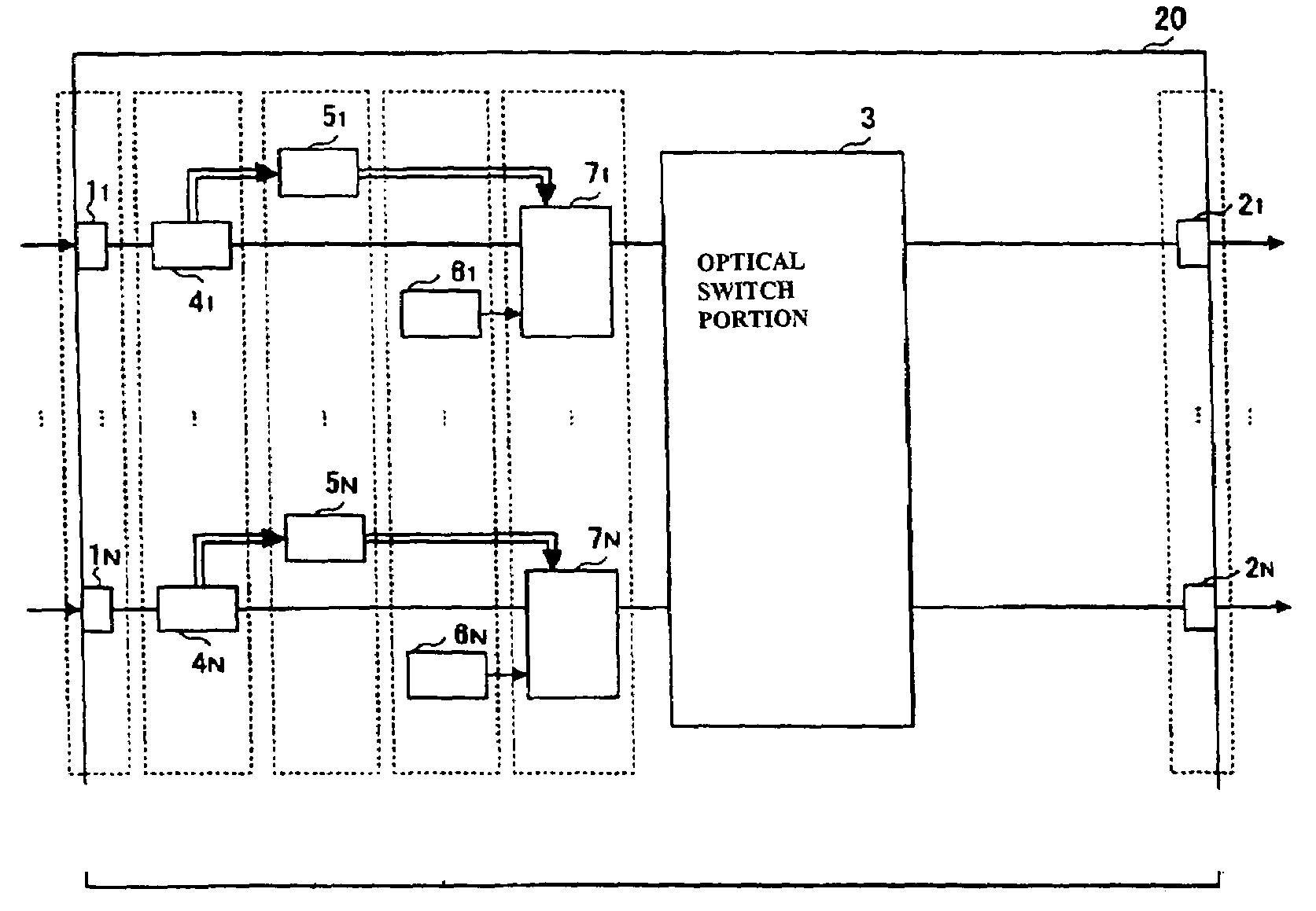
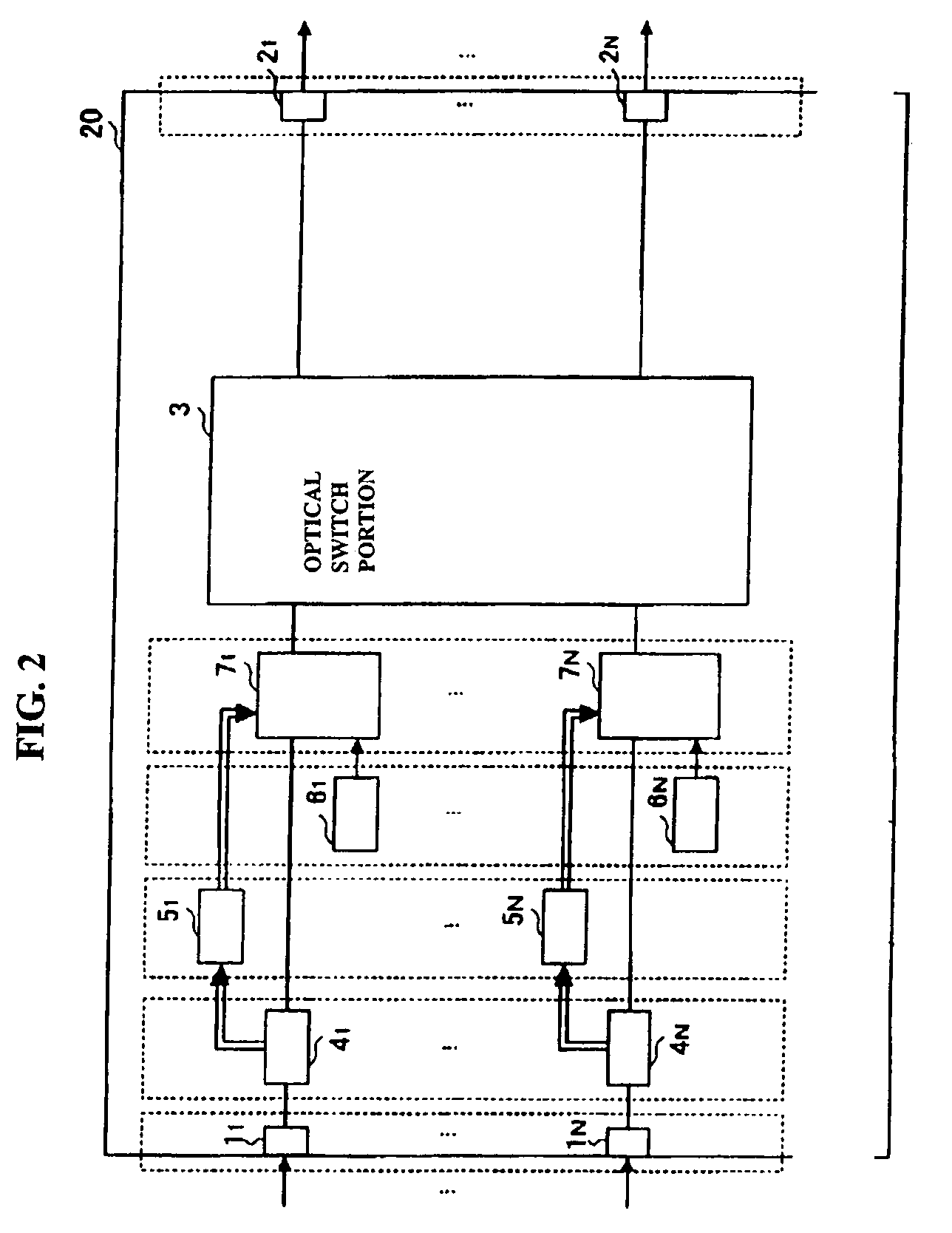
[0056]Next, the embodiments of the present invention will be described with reference to the accompanying drawings. FIG. 2 illustrates an example of structure of an optical crossconnect device of the

[0057]The optical crossconnect device of FIG. 2 comprises optical transmission signal input portions 11 to 1N, optical transmission signal output portions 21 to 2N, an optical switch portion 3, input signal monitoring portions 41 to 4N, input optical signal control portions 51 to 5N, monitoring signal generating portions 61 to 6N, and input optical signal selecting portions 71 to 7N.

[0058]Optical signals inputted to the optical transmission signal input portions 11 to 1N of the optical crossconnect device 20 are switched by the optical switch portion 3 and are then outputted from the predetermined optical transmission signal output portions 21 to 2N. The optical signals in unit of wavelength, wavelength group or optical fiber are impressed to the optical transmission signal input portion...

second embodiment

[0068]FIG. 3 illustrates an example of structure of an optical crossconnect device of the The optical crossconnect device of FIG. 2 is formed of optical transmission signal input portions 11 to 1N, optical transmission signal output portions, 21 to 2N, an optical switch portion 3, input signal monitoring portions 41 to 4N, input optical signal controlling portions 51 to 5N, monitoring signal generating portions 61 to 6N, input optical signal selecting portions 71 to 7N, and output signal monitoring portions 211 to 21N.

[0069]The optical crossconnect device 30 of the second embodiment is also provided the output signal monitoring portions 211 to 21N in the subsequent stage of the optical switch portion 3 in FIG. 2 of the first embodiment.

[0070]The output signal monitoring portion 21 is configured, for example, as illustrated in FIG. 20. Namely, the output monitoring portion 21 includes a branching portion 211 and an optical signal monitoring portion 212. An optical signal outputted f...

third embodiment

[0074]FIG. 4 illustrates an example of structure of an optical crossconnect device of the present invention. The optical crossconnect device 40 of FIG. 4 comprises optical transmission signal input portions 11 to 1N, optical transmission signal output portions 21 to 2N, an optical switch portion 3, input signal monitoring portions 41 to 4N, input optical signal controlling portions 51 to 5N, monitoring signal generating portions 61 to 6N, input optical signal selecting portions 71 to 7N, output signal monitoring portions 211 to 21N, output cut-off portions 221 to 22N, and an output optical signal controlling portion 23.

[0075]The optical crossconnect device 40 of the third embodiment is provided with the output cut-off portions 221 to 22N in the preceding stage of the optical output portion 2 (or subsequent stage of the optical switch portion 3) of FIG. 3 of the second embodiment and is further provided with the output optical signal controlling portion 23 for controlling the output ...


PUM


Abstract

An optical crossconect device comprises an optical switch, input optical level monitoring unit for monitoring optical levels of optical signals supplied to there to, signal generating unit for generating a monitoring signal to monitor the optical switch, input optical signal selecting unit for selecting the monitoring signal generated by the monitoring signal generating unit provided between the optical transmission signal input unit and the optical switch and for supplying the selected optical signal to the optical switch, and input optical signal controlling unit for controlling the input optical signal selecting unit based on an output of the input optical level monitoring unit.

Description

BACKGROUND OF THE INVENTION[0001]1. Field of the Invention[0002]The present invention relates to an optical crossconect device and a monitoring method of optical crossconnect device and particularly to an optical crossconnect device assuring higher reliability and stability of man optical switch circuit and a monitoring method of an optical crossconnect device.[0003]2. Related Art[0004]With rapid progress of the Internet, capacity of the back-born network is more and more increasing. Recently, an optical crossconnect device has been developed for realizing dynamic path setting and cancellation thereof in unit of the large capacity optical path depending on change of traffics.[0005]This optical crossconnect device can realize the switching operation without conversion of the transmitted optical signal into an electrical signal and therefore can realize reduction in size of the device even when a large capacity traffic is accommodated. However, since the optical crossconnect device ac...

Claims


Application Information

Patent Timeline
Patent Type & Authority Patents(United States)
IPC IPC(8): G02B6/26G02B6/28H04B10/07H04B10/079H04B10/27H04B10/29H04Q3/52H04Q11/00
CPCH04Q11/0005H04Q2011/0015H04Q2011/0024H04Q2011/0043H04Q2011/0083
Inventor TAKATORI, KOU
Owner FUJITSU LTD
Learn More