Communication capability measuring equipment

a technology of communication capability and measuring equipment, applied in the field of communication performance measuring equipment, can solve the problems of requiring enormous amounts of time, labor and cost, and achieve the effect of reducing the workload of an operator and accurately evaluating the communication performance on the path

Inactive Publication Date: 2006-10-10
FUJITSU LTD
View PDF4 Cites 24 Cited by
  • Summary
  • Abstract
  • Description
  • Claims
  • Application Information

AI Technical Summary

Benefits of technology

[0014]It is another object of the present invention to provide techniques of simulating data delivery based on delay models of routers which exist between the server and the client, and of accurately evaluating the communication performance on paths between the server and the client.
[0015]It is still another object of the present invention to provide a technique of precisely simulating data transfer between the server and the client, upon reflecting communication conditions of

Problems solved by technology

Enormous amounts of time, labor and costs are therefore necessary to actually measure the comm

Method used


Image

  • Communication capability measuring equipment
  • Communication capability measuring equipment
  • Communication capability measuring equipment

Examples


embodiment

[Embodiment]

[0105]First, the delay model used in the communication performance measuring equipment according to the present invention will be explained.

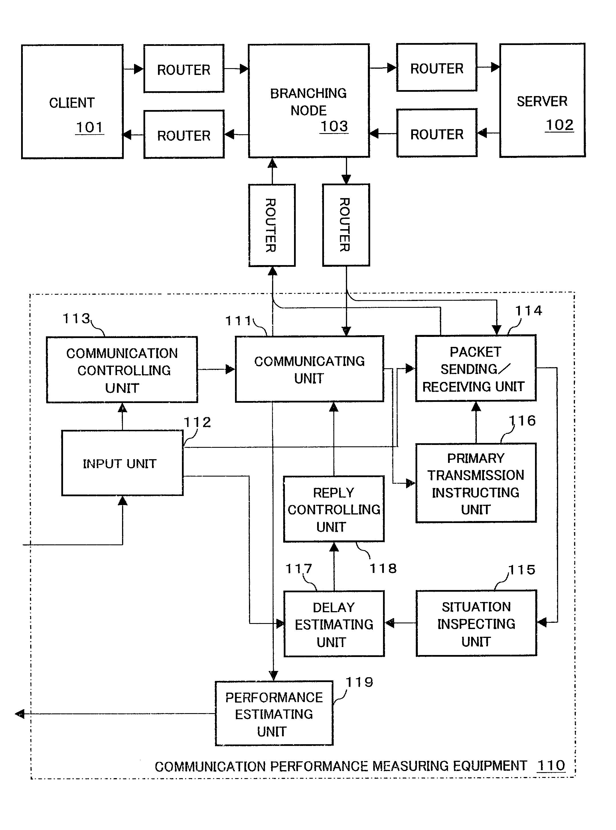
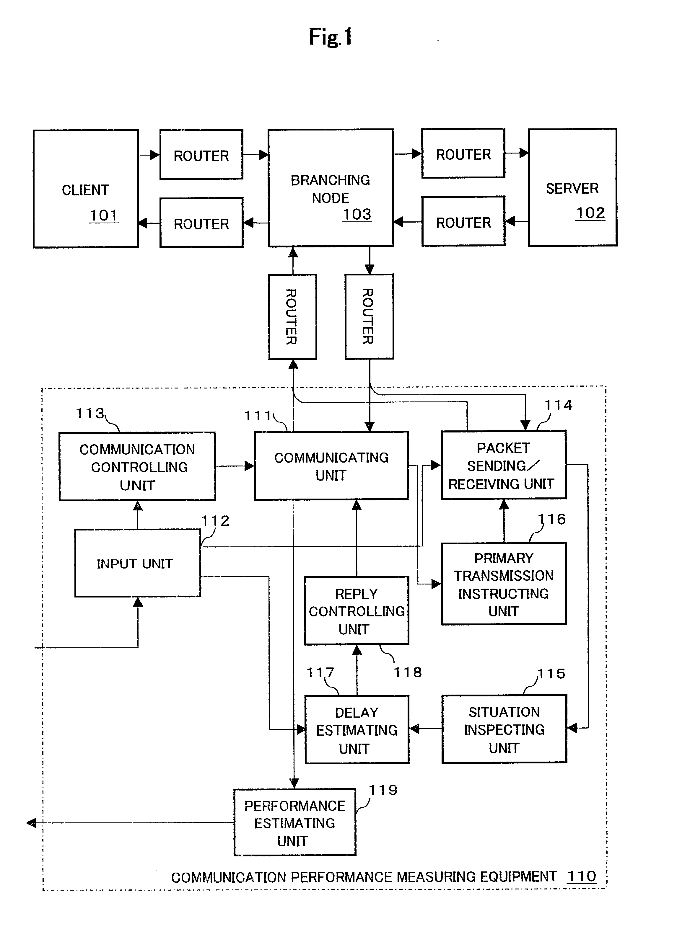
[0106]In general, a delay time Ti(sec) in transmitting a packet with a size S(bit) from an ith router R(i) to its next router R(i+i) can be expressed as Expression 1, using a queuing delay qi(sec) which occurs because of another traffic flowing into a queue of the targeted router R(i), a physical propagation delay di(sec) in a communication path to the next router R(i+i), and a rate at which the router R(i) outputs the packet to the communication path, that is, a transmission rate bi(bps).

Ti=qi+S / bi+di  (1)

[0107]Further, the delay time T in transmitting the packet with a size S through a path which is formed of n routers is the sum total of the delay times Ti corresponding to the respective routers, and therefore, it is naturally equal to the sum total of the respective factors of the delay times Ti, that is, the queuing delays qi, t...


PUM


Abstract

Every time a packet is received from a server, a communication performance measuring equipment transmits/receives a predetermined control packet to/from a client and a branching node, respectively, thereby collecting information about communication environment. Based on the information and a predetermined delay model, a delay time in delivering the same packet from the server to the client is estimated, and, according to the delay time, transmission timing of an acknowledge packet in response to the received packet is controlled. Thus, it is possible to accurately measure communication performance between an arbitrary client and an arbitrary server, no matter where the communication performance measuring equipment is physically arranged.

Description

BACKGROUND OF THE INVENTION[0001]1. Field of the Invention[0002]The present invention relates to a communication performance measuring equipment for measuring network performance in communication using a TCP / IP protocol.[0003]As personal computers and cellular phones connectable to the Internet become widespread recently, various providers have come to provide various services via the Internet to general users. Meanwhile, the general users' demands for not only receiving the various services, but also enjoying the services more comfortably are increasing.[0004]In order to meet the demands of the users, it is necessary to create an environment which enables the users to receive the services comfortably. Further, in order to determine whether or not the expansion of facilities is needed for the purpose of creation of the environment, it is necessary to precisely understand the present environment through which the users receive the services, that is, communication performance which is...

Claims


Application Information

Patent Timeline
IPC IPC(8): G01R31/08H04L69/40G06F13/00
CPCH04L43/0852H04L43/0864H04L43/0888H04L43/10H04L43/16H04L2012/5628
Inventor KIKUCHI, SHINJIADACHI, MOTOMITSUKOKUSHO, YASUHIROSATO, YOSHIHARUNAKAMURA, KATSUICHI
Owner FUJITSU LTD
Why Eureka
Try Eureka