
Output calibrator with dynamic precision

a dynamic precision, output calibrator technology, applied in the direction of instruments, pulse techniques, testing circuits, etc., can solve the problems of limiting device interchangeability, increasing the time required to achieve convergence, and limiting the interchangeability of devices,

Inactive Publication Date: 2006-10-10
RAMBUS INC
View PDF66 Cites 56 Cited by
  • Summary
  • Abstract
  • Description
  • Claims
  • Application Information

AI Technical Summary

Problems solved by technology

Unfortunately, each additional bit of resolution within the count value doubles the size of the search range for the target signal level and therefore substantially increases the time required to achieve convergence (i.e., to reach the dither condition).
This is particularly problematic in modern computing systems, where timing budgets for initialization operations are being squeezed to reduce boot times. Also, because each stepwise calibration operation is typically performed in response to one or more calibration commands from a programmed control device, increasing the calibration precision typically involves modifying system programming to increase the number of initial calibration commands.
Such modifications make legacy support for lower-precision devices difficult, limiting device interchangeability and complicating hybrid systems that include both higher- and lower-precision devices.

Method used


Image

  • Output calibrator with dynamic precision
  • Output calibrator with dynamic precision
  • Output calibrator with dynamic precision

Examples


Embodiment Construction

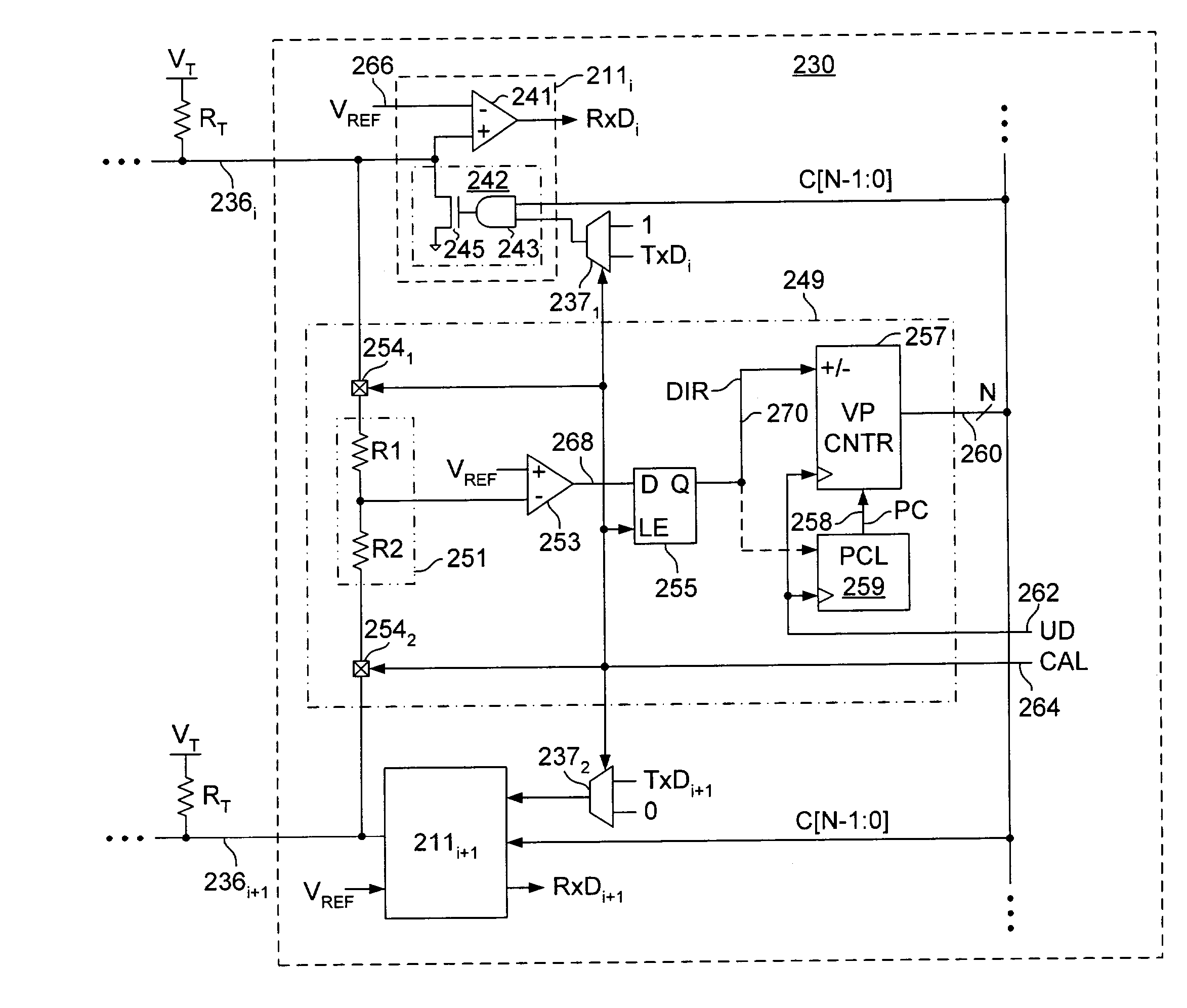
[0018]In the following description and in the accompanying drawings, specific terminology and drawing symbols are set forth to provide a thorough understanding of the present invention. In some instances, the terminology and symbols may imply specific details that are not required to practice the invention. For example, the interconnection between circuit elements or circuit blocks may be shown or described as multi-conductor or single conductor signal lines. Each of the multi-conductor signal lines may alternatively be single-conductor signal lines, and each of the single-conductor signal lines may alternatively be multi-conductor signal lines. Signals and signaling paths shown or described as being single-ended may also be differential, and vice-versa. Similarly, signals described or depicted as having active-high or active-low logic levels may have opposite logic levels in alternative embodiments. As another example, circuits described or depicted as including metal oxide semicon...


PUM


Abstract

An integrated circuit device having an output driver circuit and a control circuit. The output driver circuit outputs a first signal having a signal level according to a control value. The control circuit is coupled to receive the first signal from the output driver and adjusts the control value by a first increment until a transition event is detected. After the transition event is detected, the control circuit adjusts the control value by a second increment, the second increment being smaller than the first increment.

Description

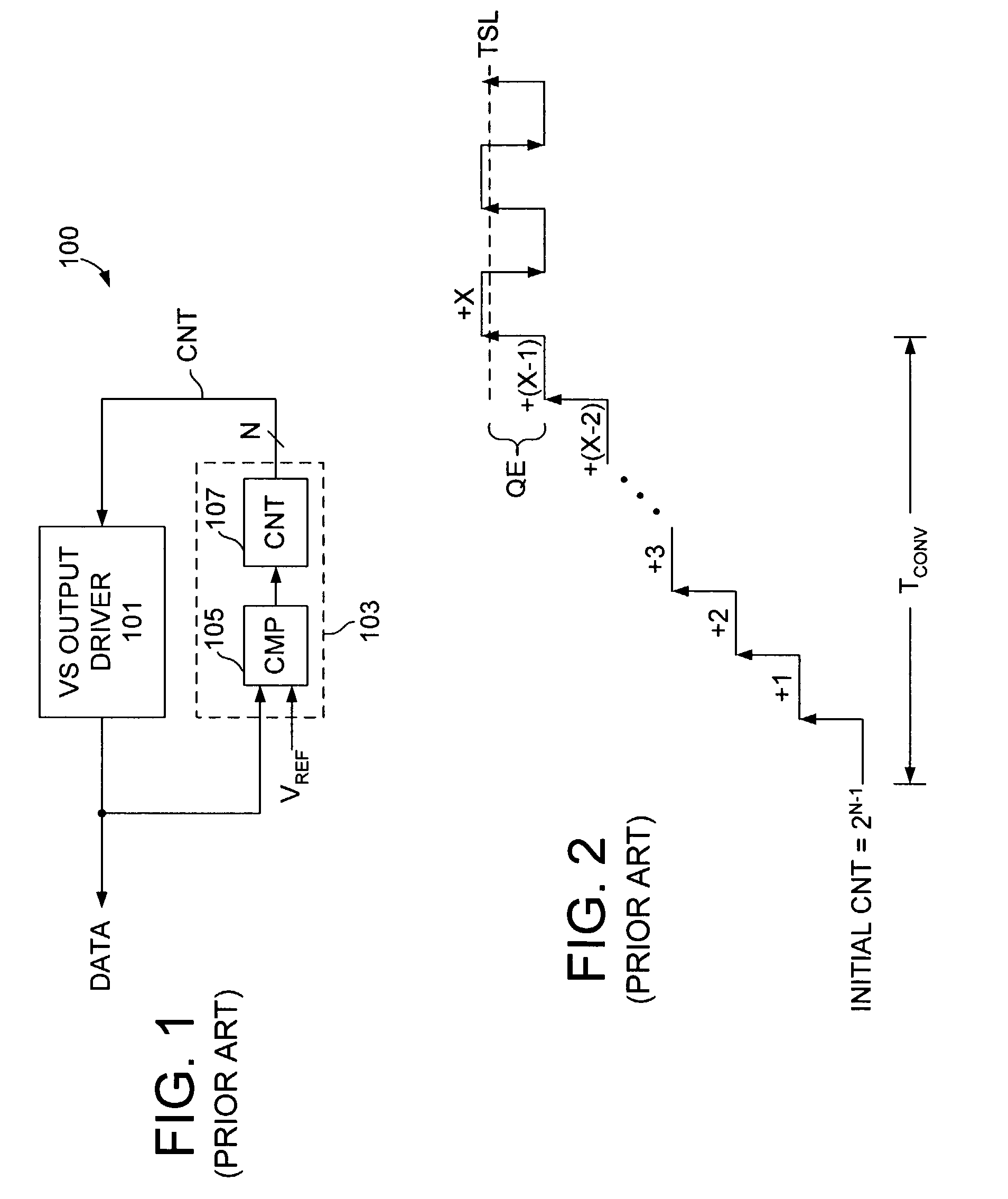
FIELD OF THE INVENTION[0001]The present invention relates generally to signaling systems, and more particularly to output driver calibration in high speed signaling systems.BACKGROUND[0002]Output calibrators are used to calibrate signaling levels in high-speed signaling systems. Through calibration, signal level variations resulting from changes in process, voltage and temperature can be reduced, increasing signaling margins and enabling higher signaling rates.[0003]FIG. 1 illustrates a prior art signaling system 100 having a variable-strength output driver 101 and an output calibrator 103. The output calibrator 103 includes a compare circuit 105 to compare a data signal (DATA) generated by the output driver 101 with a reference signal, VREF, and a counter 107 that is incremented or decremented according to the comparison result. The count value maintained within the counter (CNT) is output to the output driver 101 to control the voltage level of the data signal. Thus, the output ca...

Claims


Application Information

Patent Timeline
Patent Type & Authority Patents(United States)
IPC IPC(8): G01R35/00H03K17/16H03K19/003
CPCH03K17/167H03K19/00384
Inventor LEE, KUECK HOCKCHAN, ANDY PENG-PUI
Owner RAMBUS INC
Learn More