
System transformation connector

a technology of system transformation and connector, applied in the direction of coupling contact member, coupling device connection, electric discharge lamp, etc., can solve the problems of low production efficiency, poor signal transmission quality, and large structure design of this kind,

Inactive Publication Date: 2006-10-10
ADVANCED CONNECTEK INC
View PDF9 Cites 47 Cited by
  • Summary
  • Abstract
  • Description
  • Claims
  • Application Information

AI Technical Summary

Benefits of technology

The present invention provides a system transformation connector that can connect two different transmission interfaces and resist high frequency interference to ensure signal and data against losing. The connector has a simple structure and is convenient in assembly, improving productivity. The connector has two male / female connectors, a fixing partition plate, two circuit boards, and a plastic shell. The circuit boards are placed on the rear part of the fixing partition plate and connected to the terminals of the female connector. The connector has a terminal location effect and is easy to assemble and compact in volume. The invention improves signal transmission quality and has other embodiments.

Problems solved by technology

It is hard and inconvenient to solder by hand and it must use additional sleeve tubes for insulation to avoid short circuit among the connecting wires when the cable is soldered to the transformation connector for connection because of too many terminals, so the production efficiency is low can't reach the predetermined request; this kind of transformation connector still has a principal defect it would lose a portion of signal in data transmission for connected by soldering cable, so the user couldn't get the optimum use effect for poor signal transmission quality, and the structure design of this kind is relatively large and heavy.

Method used


Image

  • System transformation connector
  • System transformation connector
  • System transformation connector

Examples


Embodiment Construction

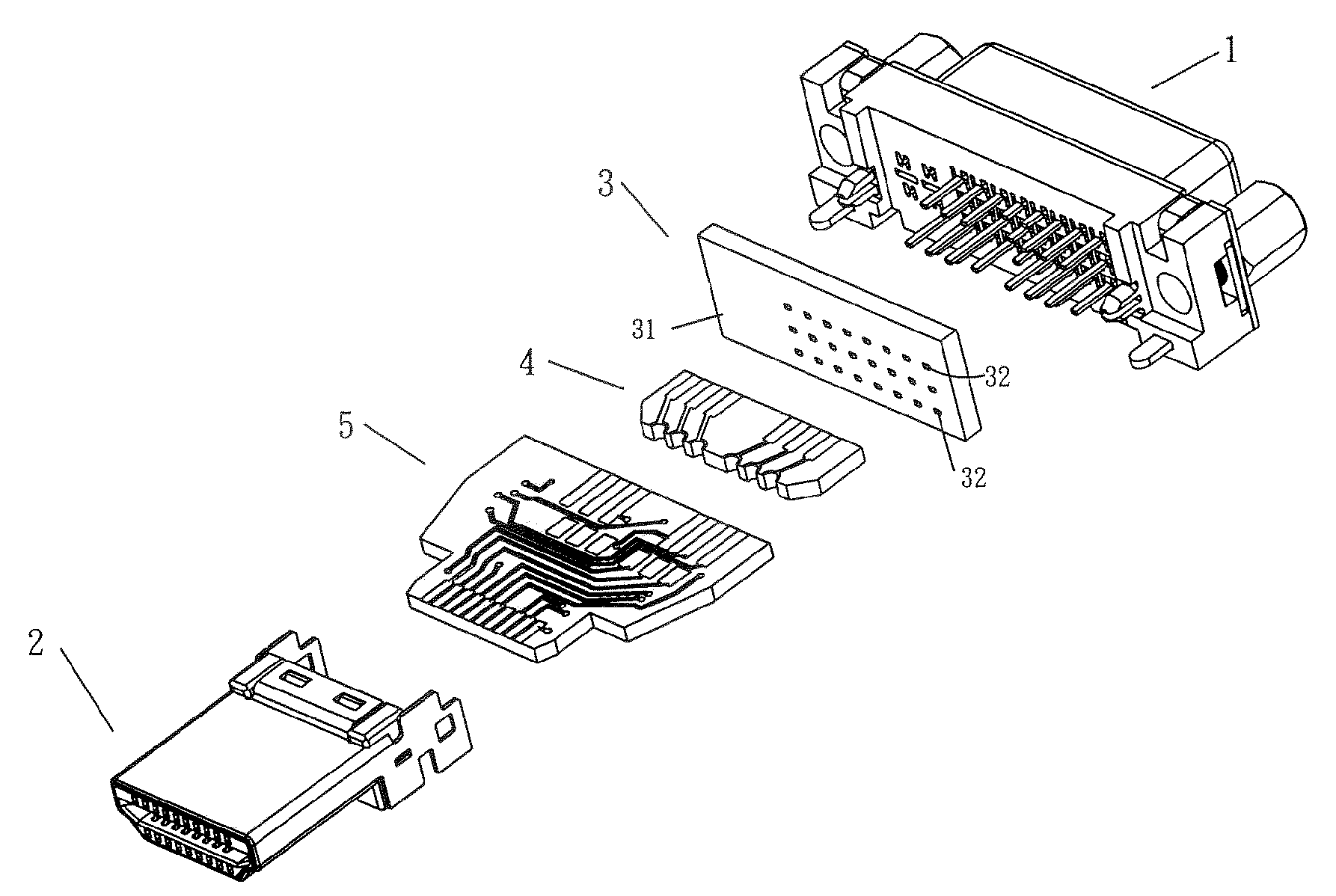
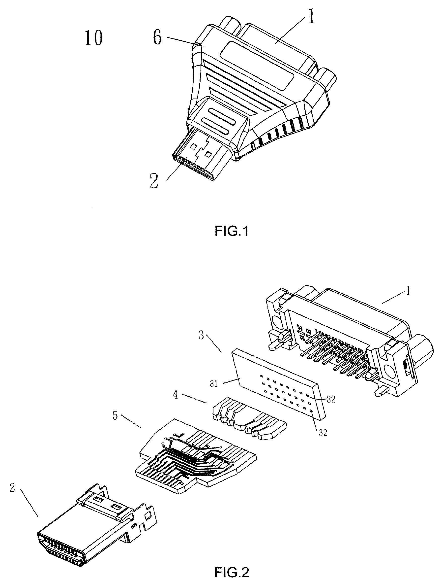
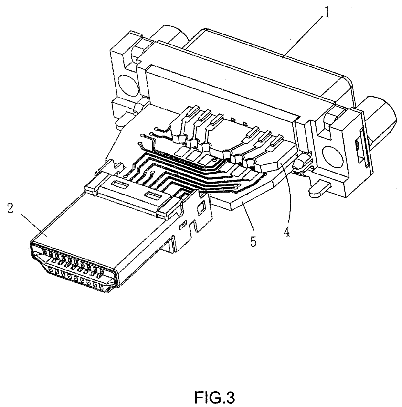
[0014]Referring to FIGS. 1 and 2, as regard to the given preferred embodiment of the invention, the system transformation connector 10 is combined by a DVI connector and an HDMI connector, the transformation connector 10 comprises a female connector 1, a male connector 2, a fixing partition plate 3 attached to the female connector 1, a circuit board 4, a circuit board 5 connected to the two different transmission interface connectors and a plastic shell 6 covering around the electrical transformation connector.

[0015]As shown in FIG. 2, the female connector 1 and the male connector 2 are two types of connectors of different transmission interfaces, each component of the connectors is a standard existing part, which is described in the earlier patent applications, so no description is given to a particular connector component again.

[0016]The fixing partition plate 3 assembled on rear part of the female connector 1 is in a rectangular structure which includes a body portion 31, on the ...


PUM


Abstract

The present invention provides a system transformation connector, which comprises two male / female connectors of different transmission interfaces, a fixing partition plate attached to the female connector, two circuit boards connected to the two male / female connectors of different interfaces and a plastic shell covering around the electrical transformation connector; therein, one of the two circuit boards is connected to the two male / female connectors of different interfaces, the other circuit board is connected to the female connector only and develops a closed circuit together with the previous circuit board through terminals to achieve signal transmission in the circuit of electronic products.

Description

BACKGROUND OF THE INVENTION[0001]1. Field of the Invention[0002]The present invention relates to a system transformation connector, especially, to a system transformation connector used for connecting two different transmission interfaces.[0003]2. Prior Arts[0004]As the time goes on, electronic product updates ceaselessly, but with regard to an enterprise, which increases a company's costs with renewing electronic device constantly, and the old electronic device can't meet requirements only in a certain domain, but it still could achieve the same effect as a new electronic device via a transformation connector, so there is no need to cause unnecessary waste for this renewal, which brings about a new commercial opportunity to the connector manufacturers.[0005]In the transformation connector used nowadays, a great majority of the transformation connectors are linked by cables. It is hard and inconvenient to solder by hand and it must use additional sleeve tubes for insulation to avoid...

Claims


Application Information

Patent Timeline
Patent Type & Authority Patents(United States)
IPC IPC(8): H01R11/00H01R13/10H01R13/66H01R31/06H01R33/94
CPCH01R31/065H01R13/6658H01R33/94H01R2201/06
Inventor HUANG, HUNG WAYDWAN, SWU LINWAN, WEI
Owner ADVANCED CONNECTEK INC
Learn More