
Torque sensor for vehicle

a technology for torque sensors and vehicles, applied in the direction of instruments, force/torque/work measurement apparatus, transportation and packaging, etc., can solve the problems of increasing the number of constituent elements, the inability to easily and quickly steer the vehicle, and the inability to smoothly carry out the gearing operation between the pinion and the rack bar. , to achieve the effect of reducing the number of elements in the torque sensor and improving productivity

Inactive Publication Date: 2006-10-10
HL MANDO CORP
View PDF7 Cites 14 Cited by
  • Summary
  • Abstract
  • Description
  • Claims
  • Application Information

AI Technical Summary

Benefits of technology

"The present invention provides a torque sensor for a vehicle with a simplified structure that reduces the number of elements in the sensor and improves productivity. The sensor housing and detection coil assembly have modified structures to fix the detection coil assembly without using a separate fixing member. This reduces the number of parts and simplifies assembly. The sensor housing has a first step, the detection coil assembly has a second step, and a groove is formed on the detection coil assembly at a position adjacent to the second step. The detection coil assembly is made of a material having a hardness larger than the sensor housing, and the detection coil assembly is fixed by the first step when the sensor housing is pressed towards the first step. The at least one detection coil assembly may be made of a plurality of detection coil assemblies, and each detection coil assembly is fixed independently. The detection coil assemblies may be assembled in the sensor housing through a lower end, and the first step and second step have inner and outer diameters respectively to prevent interference between adjacent detection coil assemblies."

Problems solved by technology

However, when the friction between the wheels and the ground is high, it is impossible to easily and rapidly steer the vehicle because an increased force is required to operate the steering wheel.
Where the friction between the wheels and the ground is high, the gearing operation between the pinion and the rack bar cannot be smoothly carried out.
However, since separate fixing members such as the fixing ring 9a and wave washer 9b must be used to fix the detection coil assemblies 6 and 7, the conventional torque sensor involves an increase in the number of constituent elements, and thus, a degradation in productivity.

Method used


Image

  • Torque sensor for vehicle
  • Torque sensor for vehicle
  • Torque sensor for vehicle

Examples


Embodiment Construction

[0030]Reference will now be made in detail to the embodiments of the present invention, examples of which are illustrated in the accompanying drawings. The embodiments are described below to explain the present invention by referring to the figures.

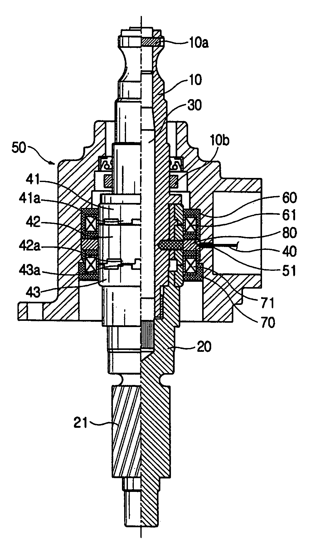
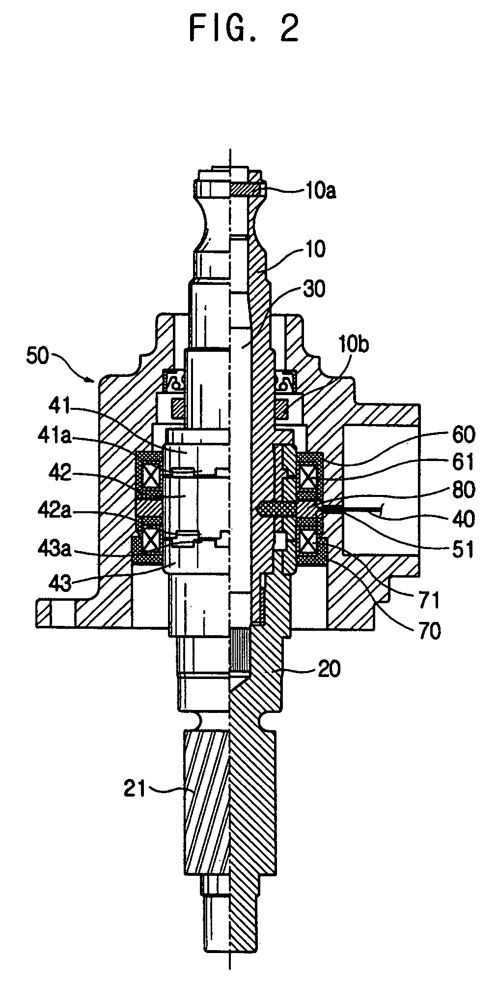
[0031]Referring to FIG. 2, a torque sensor for a vehicle according to an embodiment of the present invention is illustrated. As shown in FIG. 2, the torque sensor includes a torsion bar 30 to coaxially connect a lower end of an input shaft 10 and an upper end of an output shaft 20, a plurality of detection rings (in the illustrated case, three detection rings 41, 42 and 43) fixedly fitted around the input and output shafts 10 and 20, and a sensor housing 50 to enclose the detection rings 41, 42 and 43.

[0032]The output shaft 20 is coupled with a steering mechanism (not shown) connected to wheels (not shown) of the vehicle. The output shaft 20 is formed, at a lower end thereof, with a pinion 21 to be engaged with a rack bar (not shown) form...


PUM

PropertyMeasurementUnit
hardnessaaaaaaaaaa
outer diameteraaaaaaaaaa
inner diameteraaaaaaaaaa

Abstract

A torque sensor including a first step formed on an inner peripheral surface of a sensor housing, a second step formed on an outer peripheral surface of a detection coil assembly, the first and second steps axially supporting each other, and a groove formed on the outer peripheral surface of the detection coil assembly at a position adjacent to the second step such that the groove faces an inner surface portion of the first step, so that the first step penetrates the groove while being plastically deformed when the detection coil assembly is pressed toward the first step, thereby causing the detection coil assembly to be fixed to the inner peripheral surface of the sensor housing. Since the detection coil assembly is fixed in the sensor housing through the structural modification of the sensor housing and detection coil assembly, without using a separate fixing member, it is possible to effectively achieve the fixing of the detection coil assembly, and thus, to reduce the number of elements in the torque sensor.

Description

CROSS-REFERENCE TO RELATED APPLICATION[0001]This application claims the benefit of Korean Patent Application No. 2003-80275, filed on Nov. 13, 2003 in the Korean Intellectual Property Office, the disclosure of which is incorporated herein by reference.BACKGROUND OF THE INVENTION[0002]1. Field of the Invention[0003]The present invention relates to a torque sensor used in a power steering system of a vehicle, and more particularly to a torque sensor for a vehicle in which a detection coil assembly included in the torque sensor has a modified structure to be fixed using a sensor housing, without using a separate fixing member, thereby being capable of reducing the number of elements in the torque sensor.[0004]2. Description of the Related Art[0005]Generally, a vehicle can steer a running direction thereof in accordance with operation of a steering wheel connected to wheels via a steering shaft. However, when the friction between the wheels and the ground is high, it is impossible to ea...

Claims


Application Information

Patent Timeline
Patent Type & Authority Patents(United States)
IPC IPC(8): G01L3/02G01L3/14B62D6/10G01L3/10G01L5/00G01M17/06
CPCG01L3/101G01L3/104B62D6/10
Inventor YANG, I-JIN
Owner HL MANDO CORP
Learn More