
Programmable serializing data path

a serialization and data technology, applied in the direction of parallel/series conversion, code conversion, electrical apparatus, etc., can solve the problem of cost in the die area

Inactive Publication Date: 2006-10-03
XILINX INC
View PDF16 Cites 20 Cited by
  • Summary
  • Abstract
  • Description
  • Claims
  • Application Information

AI Technical Summary

Benefits of technology

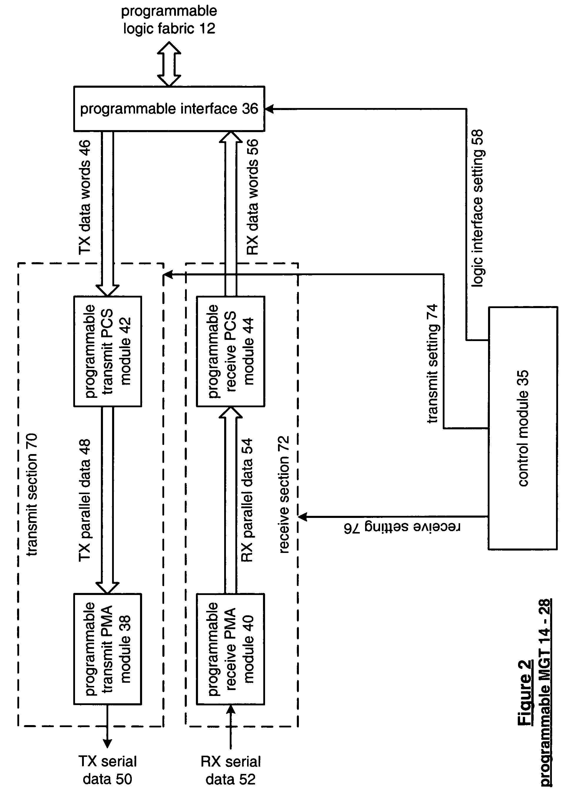
[0008]The programmable serializing data path of the present invention substantially meets these needs and others. In one embodiment, a programmable serial data path includes a programmable timing circuit and a parallel to serial module. The programmable timing circuit is operably coupled to generate a first plurality of timing signals when the width of the parallel input data is of a first multiple and to generate a second plurality of timing signals when the width of the parallel input data is of a second multiple. The parallel to serial module is operably coupled to convert the parallel input data into serial output data based on the first or second plurality of timing signals. With such a programmable serial data path, a wide variety of applications having input parallel data of varying data width multiples can readily be accommodated.
[0009]In another embodiment, a method for programmable serializing of parallel data begins by receiving the parallel data. The process continues by obtaining a data width of the parallel data by obtaining a desired serial data output rate. The process continues by generating a multiple state control sequence based on the data width of the parallel data and the desired serial data output rate. The process continues by converting the parallel data into serial data in accordance with the multiple state control sequence. With such a method, a wide variety of applications having input parallel data of varying data width multiples can readily be accommodated.

Problems solved by technology

While this solution allows the FPGA to facilitate the wide variety of applications, it is costly in die area since effectively redundant circuits are included on the die and only one is used at a time.

Method used


Image

  • Programmable serializing data path
  • Programmable serializing data path
  • Programmable serializing data path

Examples


Embodiment Construction

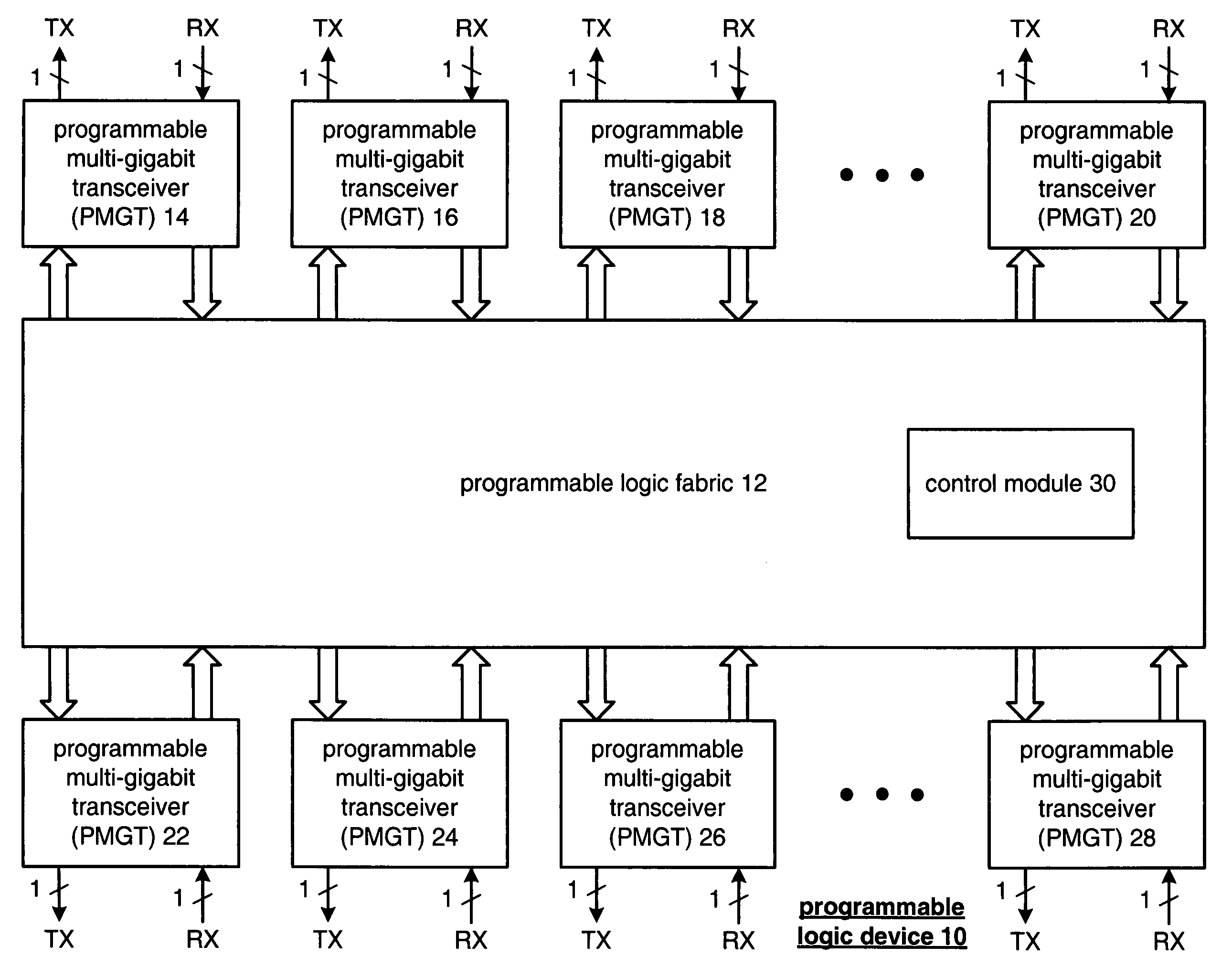
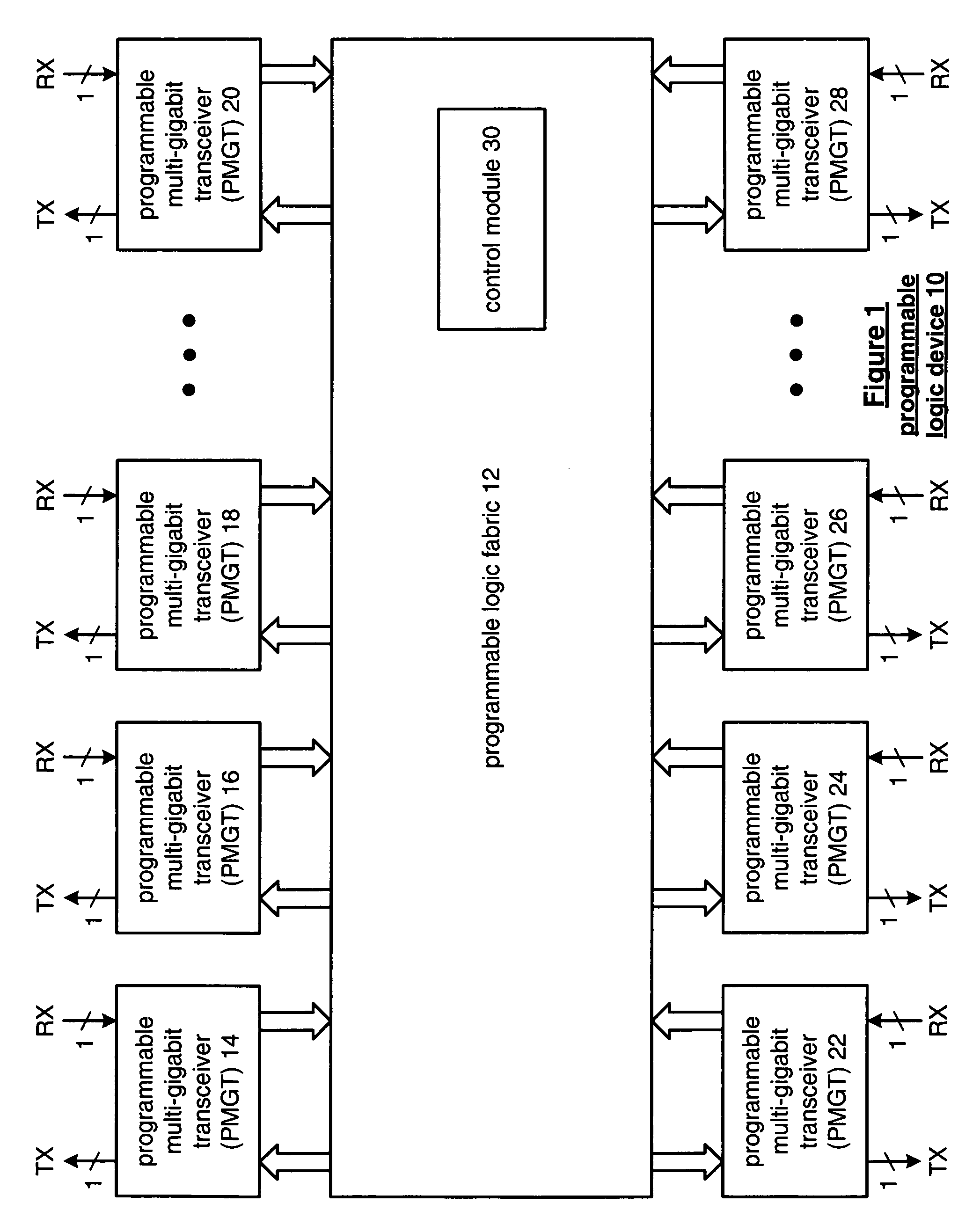
[0021]FIG. 1 is a schematic block diagram of a programmable logic device 10 that includes programmable logic fabric 12, a plurality of programmable multi-gigabit transceivers (PMGT) 14–28 and a control module 30. The programmable logic device 10 may be a programmable logic array device, a programmable array logic device, an erasable programmable logic device, and / or a field programmable gate array (FPGA). When the programmable logic device 10 is a field programmable gate array (FPGA), the programmable logic fabric 12 may be implemented as a symmetric array configuration, a row-based configuration, a sea-of-gates configuration, and / or a hierarchical programmable logic device configuration. The programmable logic fabric 12 may further include at least one dedicated fixed processor, such as a microprocessor core, to further facilitate the programmable flexibility offered by a programmable logic device 10.

[0022]The control module 30 may be contained within the programmable logic fabric ...


PUM


Abstract

A programmable serial data path includes a programmable timing circuit and a parallel to serial module. The programmable timing circuit is operably coupled to generate a first plurality of timing signals when width of parallel input data is of a first multiple and to generate a second plurality of timing signals when the width of the parallel input data is of a second multiple. The parallel to serial module is operably coupled to convert the parallel input data into serial output data based on the first or second plurality of timing signals.

Description

CONTINUING DATA[0001]This application is a divisional of application Ser. No. 10 / 659,973 filed Sep. 11, 2003, now U.S. Pat. No. 7,015,838.FIELD OF THE INVENTION[0002]This invention relates generally to general-purpose integrated circuits and more particularly to programmable logic devices.BACKGROUND[0003]Programmable devices are a class of general-purpose integrated circuits that can be configured for a wide variety of applications. Such programmable devices have two basic versions, mask programmable devices, which are programmed only by a manufacturer, and field programmable devices, which are programmable by the end-user. In addition, programmable devices can be further categorized as programmable memory devices or programmable logic devices. Programmable memory devices include programmable ready-only memory (PROM), erasable programmable read-only memory (EPROM) and electronically erasable programmable read-only memory (EEPROM). Programmable logic devices include programmable logi...

Claims


Application Information

Patent Timeline
Patent Type & Authority Patents(United States)
IPC IPC(8): H03M9/00
CPCH03M9/00
Inventor GROEN, ERIC D.BOECKER, CHARLES W.
Owner XILINX INC
Learn More