
Method of combining welding and adhesive bonding for joining metal components

a technology of adhesive bonding and welding joint, which is applied in the direction of arc welding apparatus, electron beam welding apparatus, non-electric welding apparatus, etc., can solve the problems of metallurgical incompatibilities, damage to the integrity of both the welded joint and the adhesive bond, and the combination of solid-state based welding process and chemical/mechanical bonding process (e.g., using adhesives)

Inactive Publication Date: 2006-10-03
ARCONIC INC
View PDF18 Cites 51 Cited by
  • Summary
  • Abstract
  • Description
  • Claims
  • Application Information

AI Technical Summary

Benefits of technology

[0010]The adhesive material may include a reinforcing member such as fibers or mesh. The reinforcing member may further comprise a locki

Problems solved by technology

However, a combination of fusion and solid state based welding processes with chemical / mechanical bonding processes (e.g., using adhesives) has been problematic.
Metallurgical incompatibilities arise when these two processes are applied either simultaneously at the same joining area or even when the two processes are performed sequentially.
Contact between adhesive (typically an organic material) and hot molten plasticized metals, which form during welding, results in serious damage to the integrity of both the welded joint and the adhesive bond.
In some instances, contact between the molten metal of the weld and the adhesive causes the adhesive to violently disintegrate into hydrocarbonaceous fumes which disrupts the stability of the welding process (such as the welding arc, laser beam generated plasma over a keyhole and molten pool), introduces contaminants into solidifying welds (producing gross open and bulk pores, craters, inclusions and excessive crud on the surface) and leads to inconsistent weld geometries.
If an adhesive is applied while welding is occurring, the weld may become displaced or change shape by the fumes erupting from the adhesive, become petrified in distinct locations or develop uncontrolled pores and skips, all of which lead to compromised joint quality and uniformity.

Method used


Image

  • Method of combining welding and adhesive bonding for joining metal components
  • Method of combining welding and adhesive bonding for joining metal components
  • Method of combining welding and adhesive bonding for joining metal components

Examples


Embodiment Construction

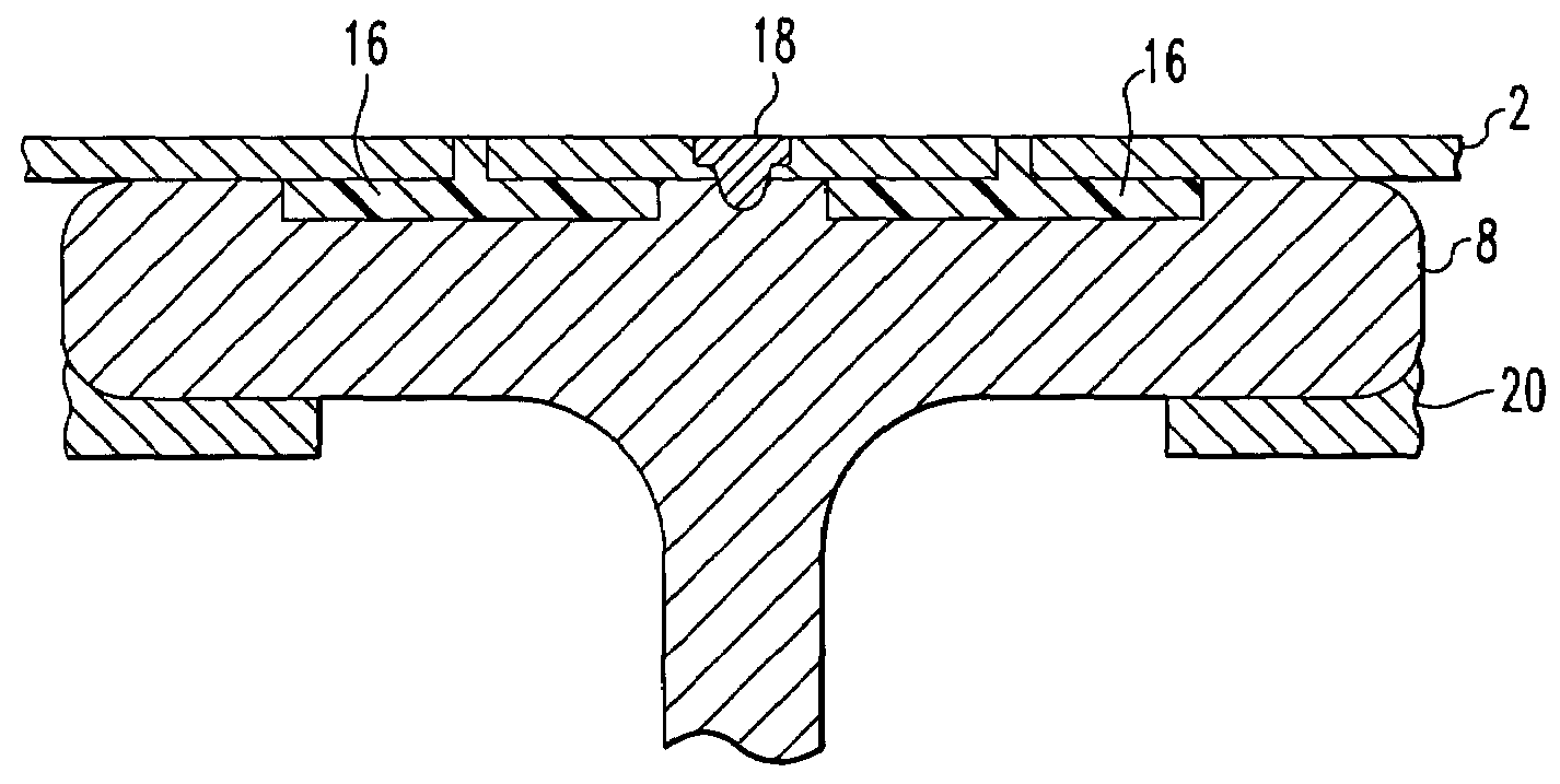
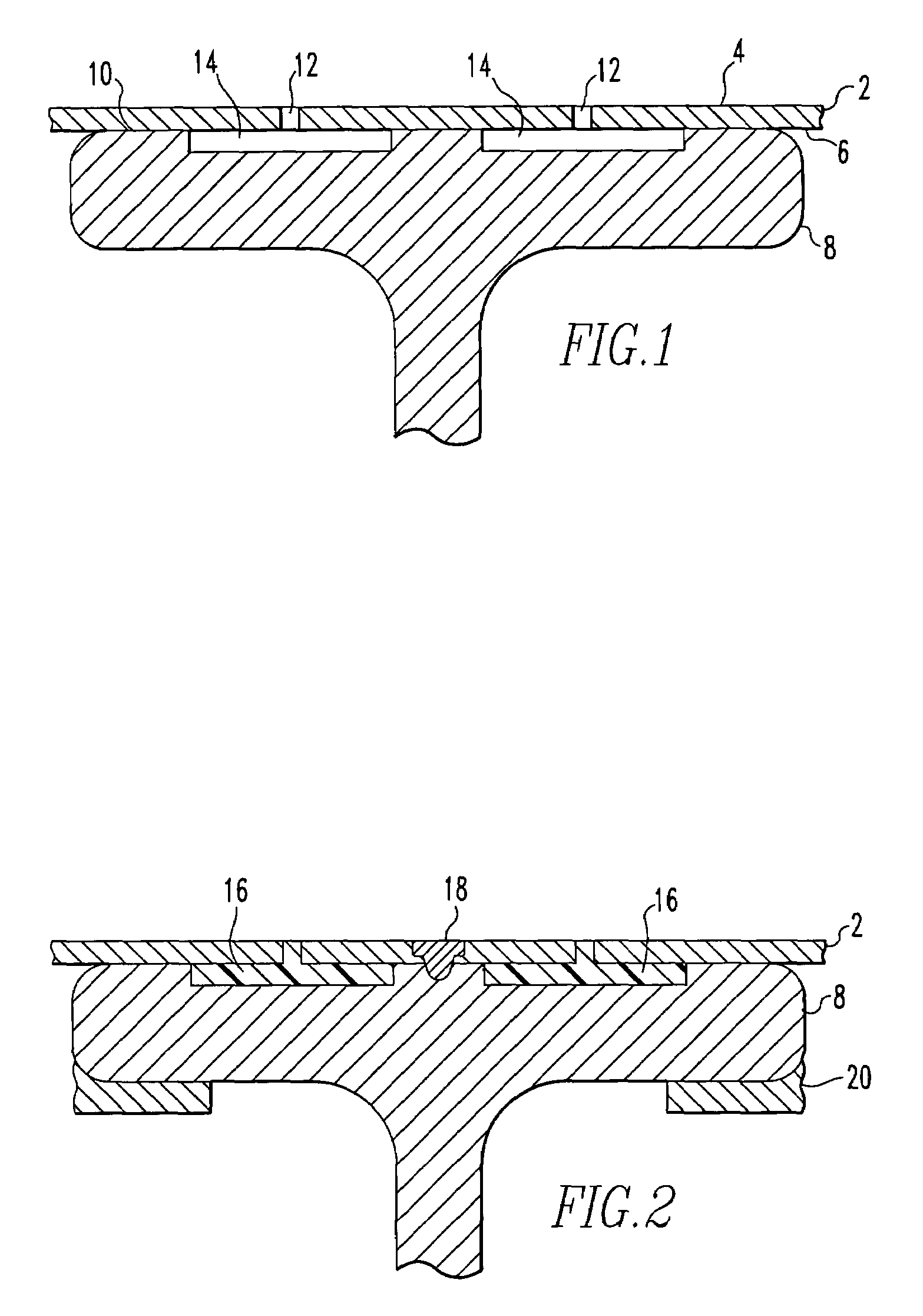
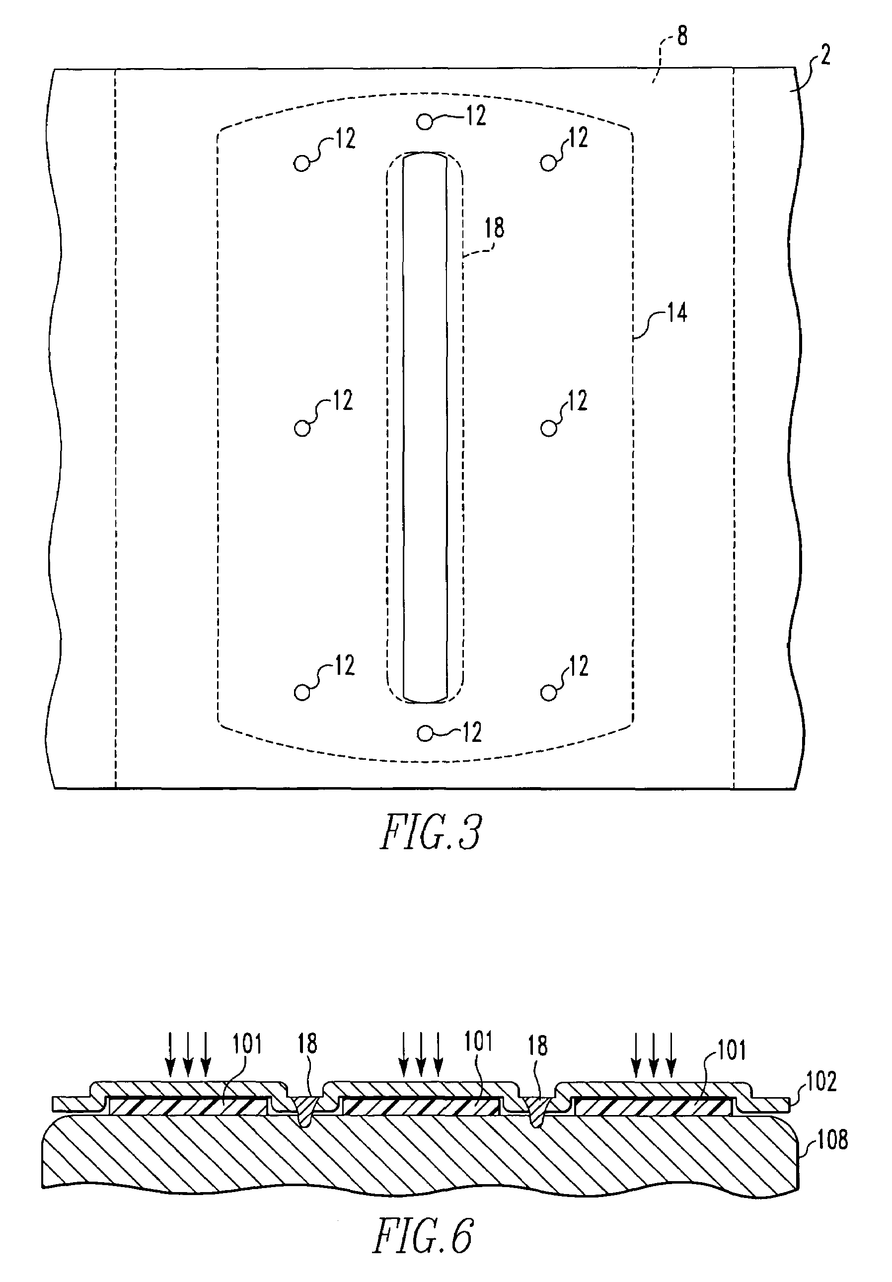
[0023]For purposes of the description hereinafter, the terms “upper”, “lower”, “right”, “left”, “vertical”, “horizontal”, “top”, “bottom” and derivatives thereof relate to the invention as it is oriented in the drawing figures. However, it is to be understood that the invention may assume various alternative variations and step sequences, except where expressly specified to the contrary. It is also to be understood that the specific devices and processes illustrated in the attached drawings, and described in the following specification, are simply exemplary embodiments of the invention. Hence, specific dimensions and other physical characteristics related to the embodiments disclosed herein are not to be considered as limiting.

[0024]The present invention is directed to a method of producing joined metal components using fusion or solid-state welding with adhesives or sealants. An important feature of the present invention is that the adverse interactions of these two types of joinin...


PUM

PropertyMeasurementUnit
Lengthaaaaaaaaaa
Timeaaaaaaaaaa
Adhesivityaaaaaaaaaa

Abstract

A method of joining metal components having the steps of depositing adhesive material between the components and welding the components together via solid-state or fusion welding. The welds are spaced apart from the adhesive material and are produced so as to prevent exposure of the adhesive material to the welding. The two types of bonds (adhesive and welding) are produced in the components separated by time and space.

Description

BACKGROUND OF THE INVENTION[0001]1. Field of the Invention[0002]The present invention relates to methods of joining metal components, more particularly to a method of joining metal components involving welding the components together and inserting an adhesive between the welded components.[0003]2. Prior Art[0004]Metal components are conventionally joined together in a variety of techniques including fusion welding, solid state bonding, chemical / mechanical bonding and mechanical engagement and locking. In fusion welding, the components are joined together through coalescence of molten metals. A weld between the components occurs when the molten metals of the components intermix and solidify. Conventional processes which are based upon fusion welding include gas metal arc welding (e.g. gas tungsten arc welding) and laser beam welding. In solid-state joining of metal components, interfacial diffusion between the mating surfaces is achieved by forcing the parts together under pressure a...

Claims


Application Information

Patent Timeline
IPC IPC(8): B32B3/30B23K28/00B32B1/06B32B3/06B32B3/10B23K9/02B23K9/235B23K11/00B23K11/08B23K11/34B23K15/00B23K20/02B23K20/12B23K26/24B23K33/00C09J5/00C09J5/06
CPCB23K9/02B23K11/002B23K11/08B23K11/34B23K15/0053B23K20/02B23K20/12B23K26/24B23K33/004C09J5/00C09J5/06B23K9/235Y10T428/24488C09J2400/163Y10T428/12347Y10T428/12236Y10T428/12486Y10T428/12264B23K2101/006
Inventor STOL, ISRAELMCCLEARY, SHERRI F.PRICE, PAULA L.
Owner ARCONIC INC
Learn More