Storage apparatus for vehicle

a technology for storage apparatuses and vehicles, applied in passenger space, roofs, transportation and packaging, etc., can solve the problems of restricting the free design of glove boxes, and achieve the effect of flexibly designing storage apparatuses, small damping force of damper devices, and reducing design restrictions

Inactive Publication Date: 2006-10-03
PIOLAX CO LTD
View PDF6 Cites 4 Cited by
  • Summary
  • Abstract
  • Description
  • Claims
  • Application Information

AI Technical Summary

Benefits of technology

[0015]According to the first aspect of the invention, the damping force control member rotates integrally with the lid so as to wind the connecting member around the guide face thereof. A winding length of the connecting member with respect to rotation angle of the lid is determined by a contour of the guide face. When the lid rotates at a fixed speed, in case where the winding length per unit angle is short and an amount of the connecting member to be drawn out is small, the damping force of the damper device will be decreased. On the other hand, in case where the winding length per the unit angle is long and the amount of the connecting member to be drawn out becomes large, the damping force of the damper device will be increased.
[0016]Accordingly, by simply adjusting the contour of the guide face of the damping force control member, an appropriate damping force can be obtained according to a change of the rotation moment of the lid by its own weight. As the results, it has become possible to flexibly design the storage apparatus, without restricting the mounting position of the damper device.
[0019]According to this structure, in the region where the guide face has the small radius of rotation, the winding length of the connecting member per the unit rotation angle is short, and therefore, the damping force generated in the damper device becomes small. By controlling in this manner the damping force of the damper device so as to be small in correspondence with the initial stage in which the rotation moment by the own weight of the lid is small, a smooth rotation of the lid can be assured.
[0022]Further, according to the invention, a guide member around which the connecting member extending from the damper device is wound, thereby to guide the connecting member to the damping force control member may be further provided. By moving around this guide member, the connecting member can be guided to the guide face of the damping force control member from a desired direction, irrespective of the mounting position of the damper device. As the results, it has become possible to freely lay out the damper device, and freeness of design will be further enhanced.
[0023]As has been described herein above, according to the invention, by simply adjusting the contour of the guide face of the damping force control member, an appropriate damping force can be obtained according to a change of the rotation moment of the lid by its own weight, without restricting the mounting position of the damper device. As the results, it has become possible to flexibly design the storage apparatus, without restricting the mounting position of the damper device.

Problems solved by technology

However, as the structure described in JP-UM-A-62-43847, the mounting position of the damper device has been determined, only from a viewpoint of controlling the damping force, and freeness of designing the glove box has been restricted.
Specifically, a size, a shape, and assembling position of the glove box have been severely designed in adjustment relative to various other components to be incorporated into the instrument panel of the vehicle.

Method used


Image

  • Storage apparatus for vehicle
  • Storage apparatus for vehicle
  • Storage apparatus for vehicle

Examples


Embodiment Construction

[0034]Now, an embodiment of the invention will be described in detail, referring to the drawings.

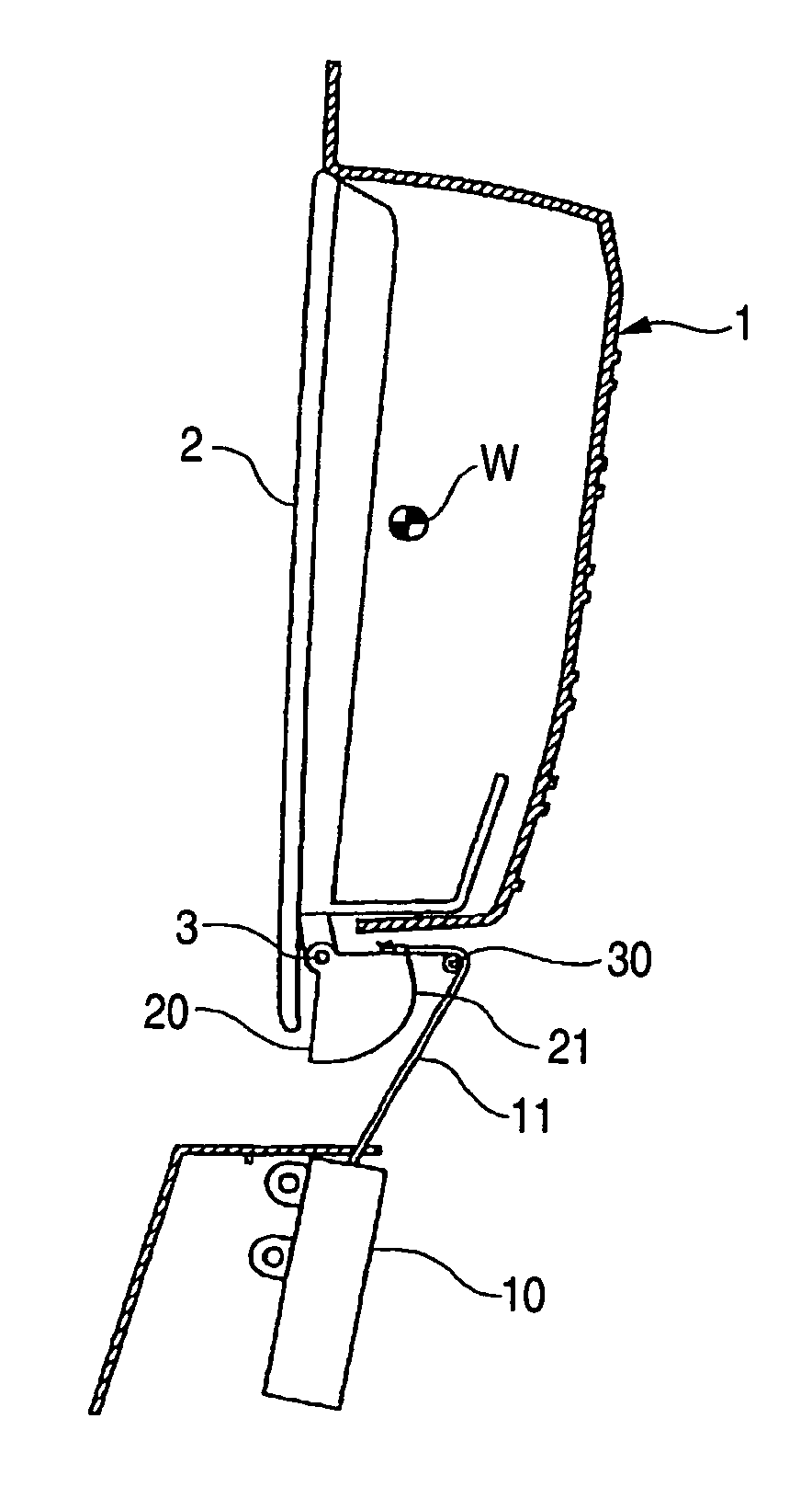
[0035]FIG. 1 is a sectional side view showing an embodiment in which the invention has been applied to a glove box of an automobile.

[0036]The glove box is constructed in such a manner that a storage space is formed inside a body 1, and a lid 2 is attached to an opening on its front face so as to be opened or closed. The lid 2 is attached to the body 1 at both sides of its lower end in a manner rotatable around the lower end as a pivot 3. The lid 2 is in almost upright position in its completely closed state (the state as shown in FIG. 1). In this state, a center of gravity W of the lid 2 lies at a position somewhat inward (a right side in the drawing) from a vertical line extending above the rotation pivot 3. Accordingly, a rotation moment of the lid 2 by its own weight is exerted in a direction of closing the lid 2 (a clockwise direction in FIG. 1), and keeps the lid 2 in the completely...


PUM


Abstract

In a storage apparatus for a vehicle including a lid which can rotate about a pivot, and a damper device having a cord-like connecting member and adapted to generate damping force against pulling force from the connecting member, wherein a connecting wire (the connecting member) is pulled, when the lid rotates in one direction, thereby to generate the damping force in the damper device, it is so constructed that a damping force control member having a guide face for the connecting wire is fixed to the lid, and when the lid has rotated in a direction of receiving the damping force, the connecting wire is wound around the guide face and pulled.

Description

BACKGROUND OF THE INVENTION[0001]1. Field of the Invention[0002]The present invention relates to a storage apparatus for a vehicle, which has a lid rotatable about a pivot, such as a glove box provided on an instrument panel of the vehicle.[0003]2. Description of the Related Art[0004]In many storage apparatuses for vehicles, such as glove boxes, there are provided damper devices in order to restrain sudden rotation of a lid by its own weight. As the damper device of this type, a damper of air system as shown in JP-UM-A-5-76894, for example, has been proposed.[0005]The conventional damper device of this type, though not specifically illustrated herein, mainly includes three components, namely, a cylinder, a piston, and a pulling wire. The piston provided with a seal ring on its periphery is slidably contained in a cylinder and urged by a compressive coil spring in one direction. Meanwhile, a guide cap is fitted to an opening of the cylinder at its front side, and one end of the pulli...

Claims


Application Information

Patent Timeline
Patent Type & Authority Patents(United States)
IPC IPC(8): B60N3/12B60R7/06B60R7/04B60R11/00B60R11/02B60R13/02E05F5/06
CPCB60R7/04B60R11/00B60R11/0264B60R13/0256B60R2011/0005B60R7/06B60R2011/0085
Inventor ICHIOKA, HIROAKIMATSUMOTO, TAKASHI
Owner PIOLAX CO LTD
Why Eureka
Try Eureka