Eureka AIR delivers breakthrough ideas for toughest innovation challenges, trusted by R&D personnel around the world.

Three-dimensional display apparatus and method

a display apparatus and three-dimensional technology, applied in the direction of instruments, static indicating devices, optical elements, etc., can solve the problems of unnatural use of lc shutter glasses in a television conference, difficult to show an object, tired eyes of viewers, etc., and achieve the effect of small size and simple structur

Inactive Publication Date: 2006-09-26
PIONEER CORP
View PDF7 Cites 22 Cited by
  • Summary
  • Abstract
  • Description
  • Claims
  • Application Information

AI Technical Summary

Benefits of technology

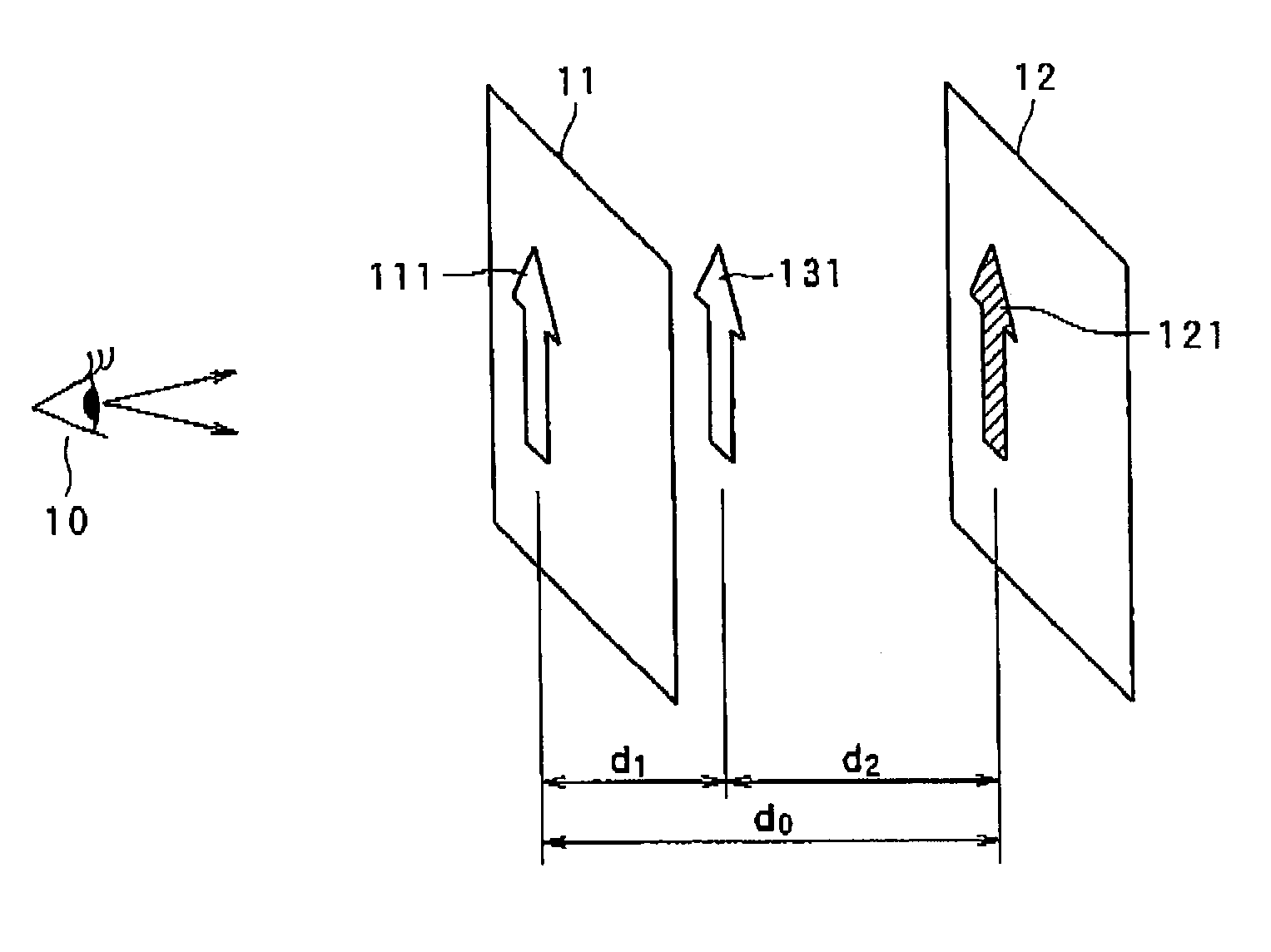
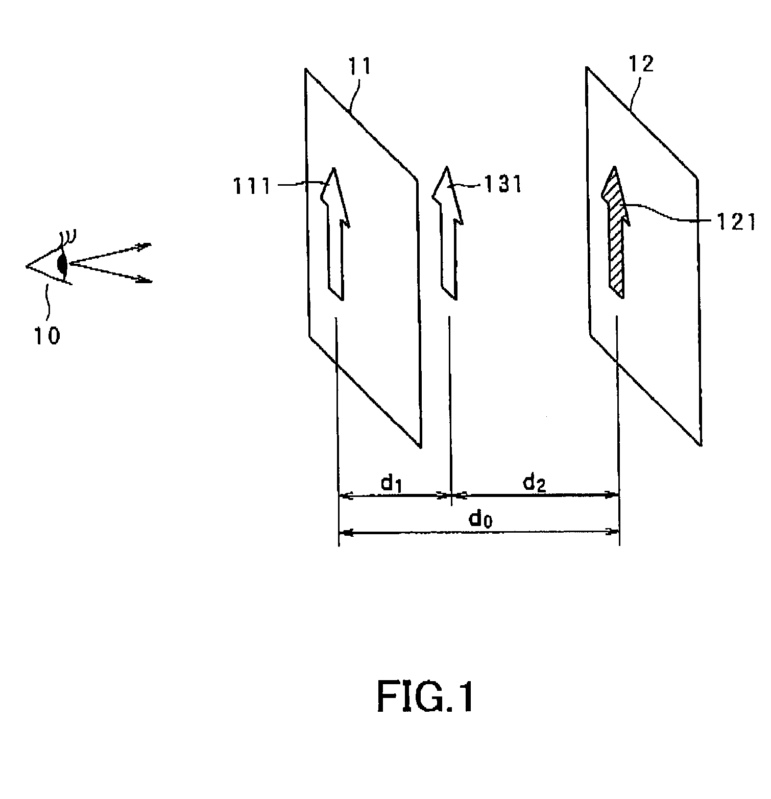
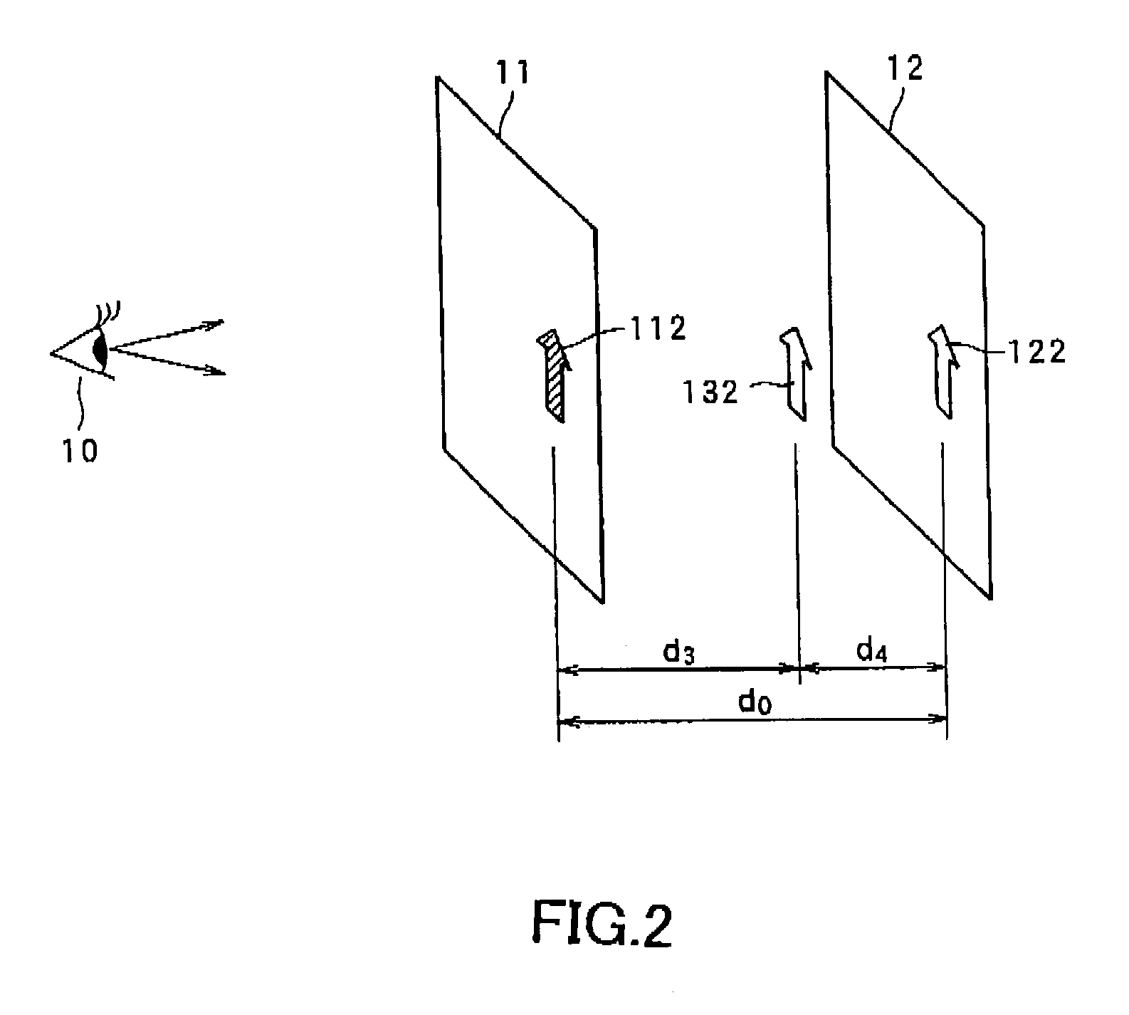
[0011]It is therefore an object of the present invention to provide a 3D display apparatus and a 3D display method of the brightness modulation type, which can show the advanced 3D image with a relatively small-sized and simple structure.

Problems solved by technology

For example, it is unnatural to use the pair of LC shutter glasses in a television conference.
That is to say, although the LC shutter glass method can satisfy the parallax of two eyes and the congestion since there is a focusing face on a surface of the image, this contradiction makes the viewer's eyes so tired.
However, according to the cubic-volume method, it is difficult to show an object, which is placed at a middle position of the two of the 2D display apparatuses or changes its position in a great magnitude toward the depth direction from the viewer, because the several 2D images are discretely positioned in the depth direction from the viewer.
However, this brightness modulation method has such a problem that the 3D display apparatus cannot show the image of a semitransparent object or the image through which the viewer can watch an object at the back of the image.
However, in this method, the 3D display apparatus is large in scale and is so complicated that the 3D display apparatus cannot meet general requirements of miniaturization, lightweight and cost reduction in the concerned technical field because the 3D display apparatus includes a plurality of optical elements such as half mirrors and the like.

Method used


Image

  • Three-dimensional display apparatus and method
  • Three-dimensional display apparatus and method
  • Three-dimensional display apparatus and method

Examples


first embodiment

[0104]the image displaying device will be explained with reference to FIG. 5.

[0105]As shown in FIG. 5, the first display unit 11 of the present embodiment has a displaying device, which displays the image by self-emitting (as indicated by self-emitted lights L1 and L2) and which passes therethrough the light L3 coming from the back side thereof, for example the EL element. Accordingly, the viewer 10 can watch the image, which is displayed on the second display unit 12, through the first display unit 11 in addition to the image which is displayed on the first display unit 11. This device can make the 3D display apparatus small-sized.

2nd EMBODIMENT OF IMAGE DISPLAYING DEVICE IN 3D DISPLAY APPARATUS

second embodiment

[0106]the image displaying device will be explained with reference to the FIG. 5 in the same way.

[0107]As shown in FIG. 5, the first display unit 11 of the present embodiment has a displaying device, which displays the image by self-emitting (as indicated by self-emitted lights L1 and L2) and which passes therethrough the light L3 coming from the back side thereof, for example the EL element. The displaying device, the amount of the light of the surface of which is greater than that of the back surface, is employed in the second embodiment. It is possible to actualize such a displaying device by employing an illuminating element of the displaying device, which emits the light from the surface more than from the back surface. The light L2 emitted from the back face reaches at the second display unit 12 as a light L4 and a reflection light L5 on the surface of the second display 12 returns to the first display unit 11. The reflection light L5 may more or less harm for showing the imag...

third embodiment

[0108]the image displaying device will be explained with reference to the FIG. 6.

[0109]As shown in FIG. 6, the first display unit 11 of the present embodiment has a displaying device, which displays the image by self-emitting (as indicated by self-emitted lights L1 and L2) and which passes therethrough the light L3 coming from the back side thereof, for example the EL element. Further, the back surface of the displaying device is provided with a half mirror 13. The light L2 emitted from the first display unit 11 toward the second display unit 12 is in fact cut off by the half mirror 13 and, on the other hand, the light L3 emitted from the second display unit 12 can pass through the half mirror 13 and the first display unit 11. Therefore, the viewer 10 can watch the image which is displayed on the second display unit 12 through the half mirror 13 and the first display unit 11. It is possible to improve the quality of the 3D image because of preventing the light L2 which is emitted fr...


PUM


Abstract

A 3D display apparatus (2) is provided with: a plurality of displaying devices (11, 12) which are arranged on a visual line of a viewer (10) in series at a predetermined interval; and a controlling device (31–39) for controlling the displaying devices to respectively display images, so as to show a three dimensional image for the viewer. At least one (11) of the displaying devices except for a displaying device (12) which is positioned farthest from the viewer has an image displaying surface having both of a self-emitting property and a light transparency property.

Description

BACKGROUND OF THE INVENTION[0001]1. Field of the Invention[0002]The present invention relates to a 3D (three dimensional) display apparatus and method of a brightness modulation type (i.e., a luminance or intensity modulation type), which can show a 3D) image for a viewer by displaying a plurality of images of an object with changing the brightness of the images and overlapping the images on each other from a view point of the viewer.[0003]2. Description of the Related Art[0004]There is a LC (Liquid Crystal) shutter glass method or the like as a 3D display apparatus, which can show a 3D image of motion picture and can electrically rewrite the 3D) image. This LC shutter glass method shows the 3D image by inputting an image signal, which is composed of image data including parallax information obtained by shooting a picture of a 3D object from several directions, into a 2D display apparatus. A viewer or observer wears a pair of LC shutter glasses. When an odd field image is on the 2D ...

Claims


Application Information

Patent Timeline
IPC IPC(8): G06T15/00G03B35/18H04N13/395G02B27/22G03B35/08H01L51/50
CPCH04N13/0495H04N13/395
Inventor KURODA, KAZUOSUGIURA, SATOSHIYANAGISAWA, SHUUICHI
Owner PIONEER CORP
Why Eureka
Eureka Blog
Learn More