
Programmable resistance seam welding apparatus and method

a resistance seam and welding apparatus technology, applied in the direction of welding with roller electrodes, manufacturing tools, rolling electrodes, etc., can solve problems such as welding limitations, and achieve the effects of reducing welding current, small welding contact points, and reducing the amount of contacting surface area

Inactive Publication Date: 2006-09-26
GM GLOBAL TECH OPERATIONS LLC
View PDF8 Cites 2 Cited by
  • Summary
  • Abstract
  • Description
  • Claims
  • Application Information

AI Technical Summary

Benefits of technology

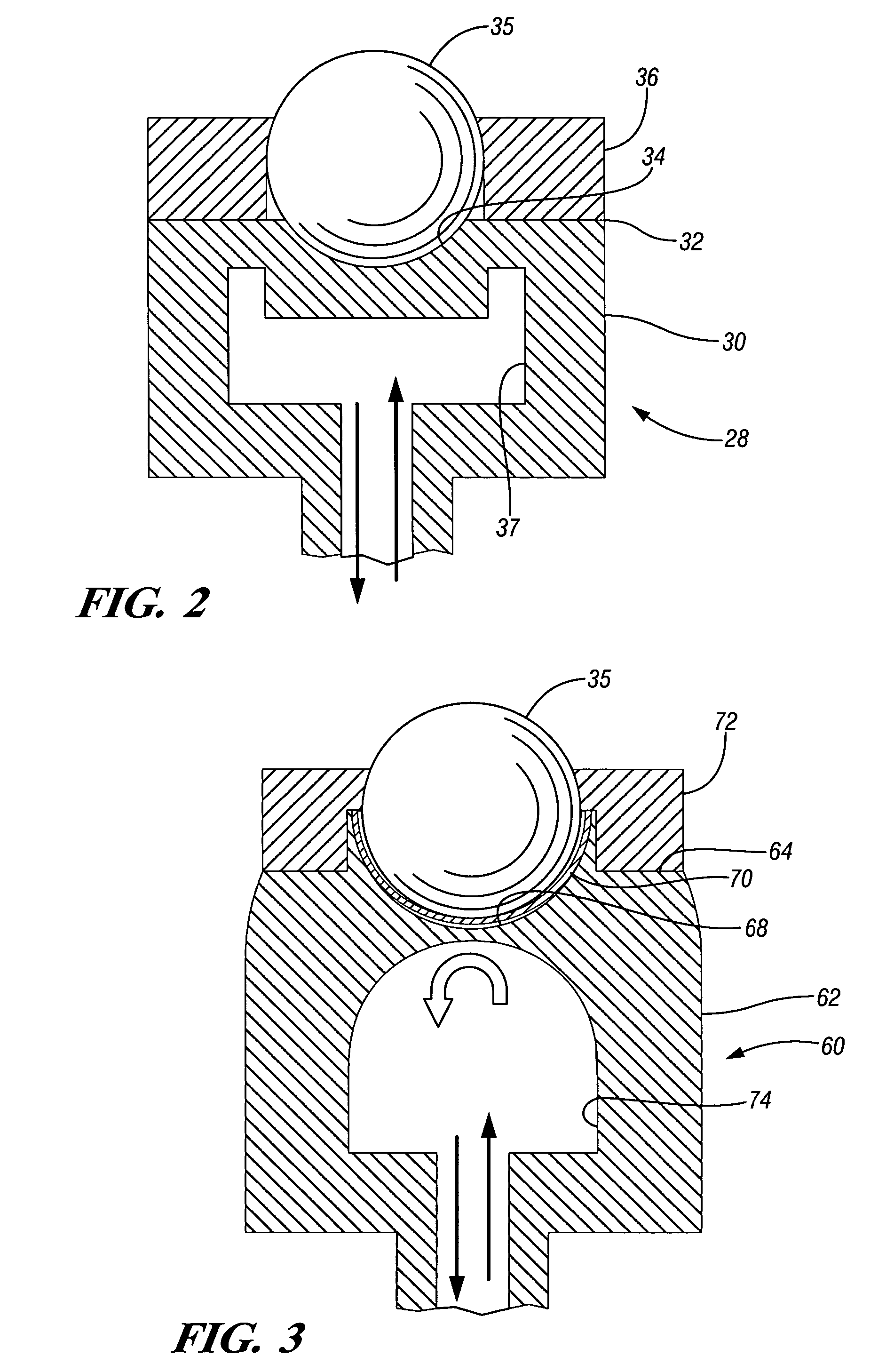
The present invention provides a resistance seam welding apparatus with two movable positioners carrying ball electrodes that can be programmed to move along a seam line and clamp on opposite sides of workpieces to form a resistance seam weld. The apparatus can also include a holding fixture or support for carrying a structural assembly formed of stacked workpieces. The use of ball electrodes allows for smaller welding contact points, reducing the amount of welding current required and allowing the positioners to move over curves and bends in the workpieces without losing contact. The technical effects of the invention include improved weld quality, efficiency, and flexibility.

Problems solved by technology

The larger contact area of a roller electrode also creates welding limitations when the workpieces to be joined are contoured or non-planar.

Method used


Image

  • Programmable resistance seam welding apparatus and method
  • Programmable resistance seam welding apparatus and method
  • Programmable resistance seam welding apparatus and method

Examples


Embodiment Construction

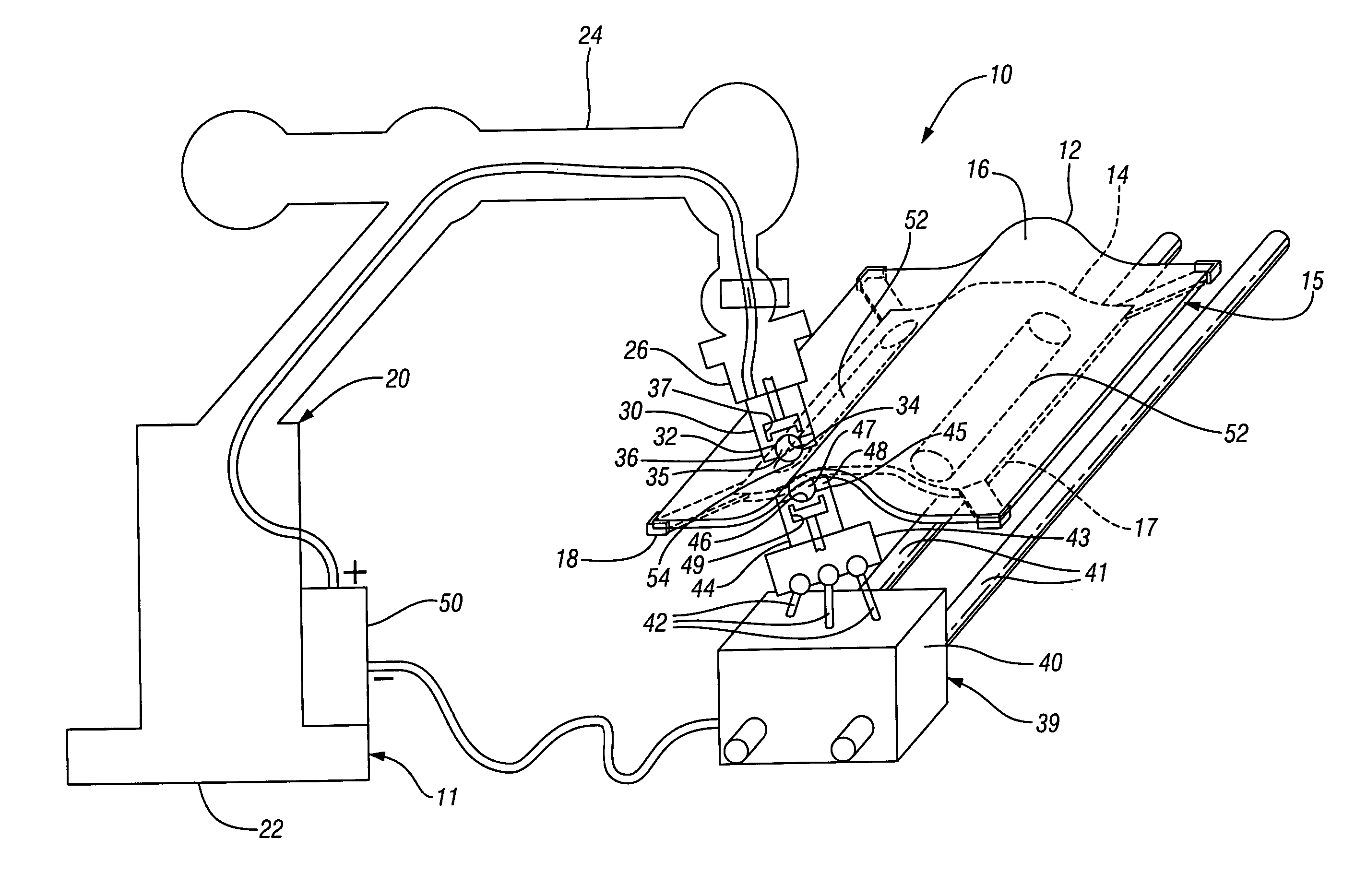
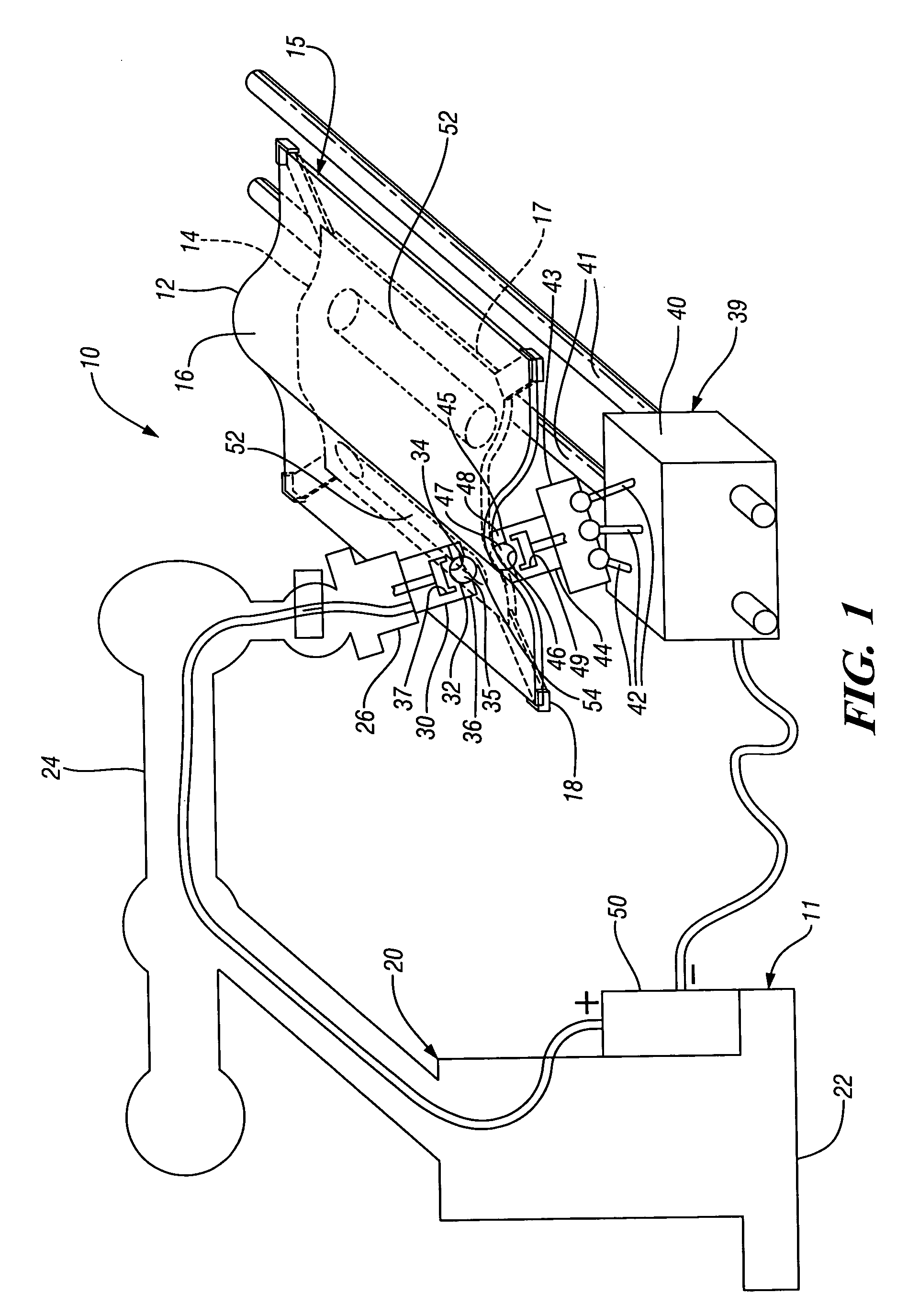
[0015]Referring first to FIG. 1 of the drawings, numeral 10 generally indicates a workstation containing an apparatus 11 configured for resistance seam welding of workpieces. A temporary assembly of workpieces, such as a tunneled floor pan 12 and a tunnel undershield 14 are supported in the apparatus for welding into a structural assembly 15 in the form of a floor pan assembly for a vehicle. The structural assembly 15 includes an upper side 16 of the floor pan 12 and a lower side 17 of the undershield 14.

[0016]The resistance seam welding apparatus 11 includes a suitable holding fixture or support 18 adapted to carry the temporary assembly of the structural floor pan 12 and undershield prior to and during welding of these workpieces into the structural assembly 15.

[0017]The resistance seam welding apparatus 11 further includes a first positioner in the form of a robot 20. If appropriate, any other suitable form of programmable positioner may be substituted for the robot 20 within the...


PUM

PropertyMeasurementUnit
temperatureaaaaaaaaaa
electrically conductiveaaaaaaaaaa
resistance electrically conductive heat resistantaaaaaaaaaa

Abstract

A resistance welding apparatus having a pair of programmable ball electrodes carried on universally movable positioners. The positioners are programmed to move the ball electrodes simultaneously along a seam line so that the ball electrodes clamp and support opposite sides of a pair of stacked workpieces and are electrically charged to form resistance seam welds along the seam lines to connect the workpieces.

Description

TECHNICAL FIELD[0001]This invention relates to resistance seam welding and, more particularly, to a resistance seam welding apparatus and method.BACKGROUND OF THE INVENTION[0002]Resistance seam welding is known in the art for joining metal workpieces. The workpieces may be stacked or otherwise held in temporary assembly. The workpieces are then clamped between a pair of roller electrodes, which locally compress the workpieces. The electrodes are energized, causing electrical current flow through the workpieces to locally heat the workpieces between the electrodes and thereby form a weld. During this time the workpieces and the rollers are moved relative to one another to elongate the weld and thereby form a seam weld between the workpieces.[0003]Roller electrodes commonly have a larger contact area than conventional electrodes, which distributes welding current over a larger workpiece area. Thus a greater flow of electric current is required than with conventional electrodes to heat...

Claims


Application Information

Patent Timeline
Patent Type & Authority Patents(United States)
IPC IPC(8): B23K11/06
CPCB23K11/3045B23K11/087
Inventor SUN, PETER C.WANG, PEI-CHUNG
Owner GM GLOBAL TECH OPERATIONS LLC
Learn More