Semiconductor device manufacturing method
a manufacturing method and semiconductor technology, applied in the direction of semiconductor devices, basic electric elements, electrical appliances, etc., can solve the problems of unstable characteristics of withstanding voltage, increase of on resistance, and many other problems, to achieve the effect of preventing an on resistance from increasing, reducing production costs, and saving weigh
- Summary
- Abstract
- Description
- Claims
- Application Information
AI Technical Summary
Benefits of technology
Problems solved by technology
Method used
Image
Examples
first embodiment
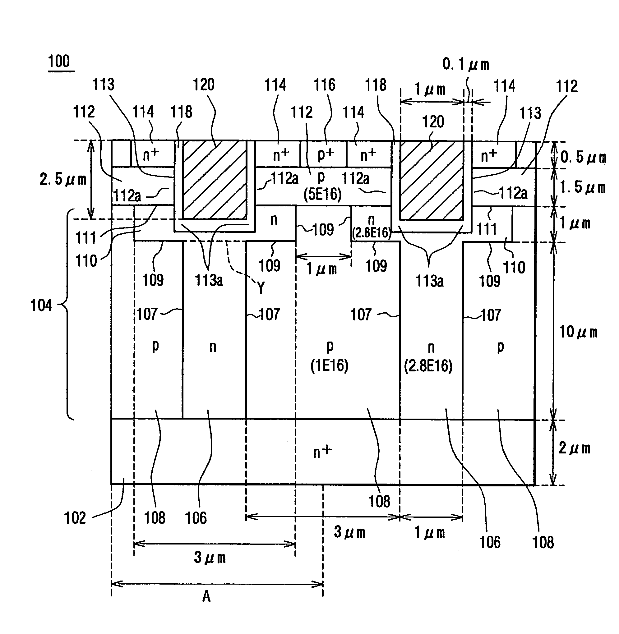
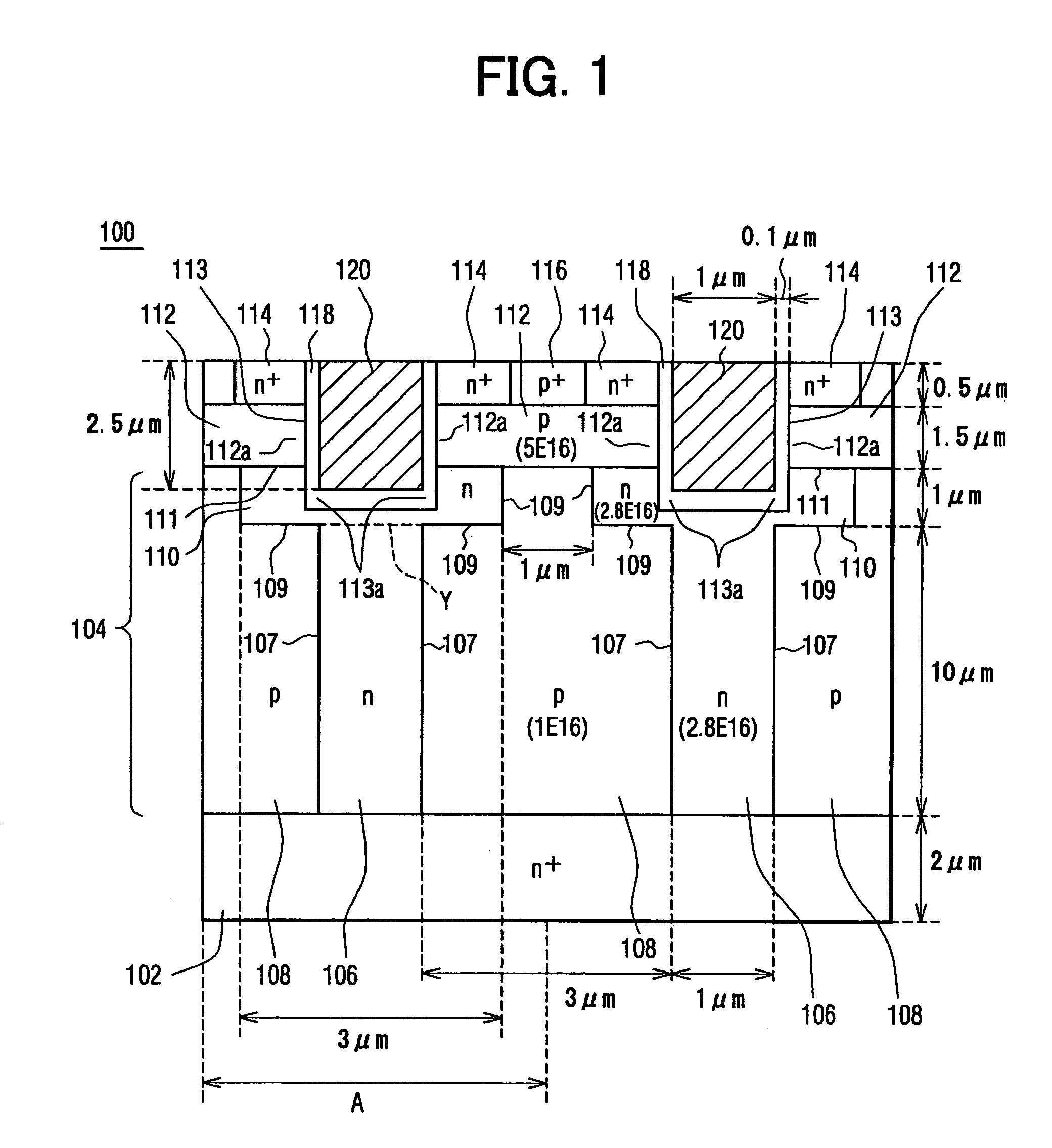
[0058]A vertical semiconductor device 100 of a first embodiment of the present invention is shown in a sectional view in FIG. 1. A width A shown in a lower area of FIG. 1 shows a unit structure that is repeatedly formed in a horizontal direction (from side to side) of FIG. 1.
[0059]The semiconductor device 100 forms metal oxide semiconductor (MOS) field effect transistor (FET) structure of a U trench type (U-shaped gate trench 113). The semiconductor device 100 is used for a motor of a vehicle, or a power converter or power control of electrical appliances for home use.
[0060]The semiconductor device 100 includes a drain region 102, a drift region 106, a silicon region 108, a body region 112, an upper silicon region 110, a source region 114, and a gate 120.
[0061]The drain region 102 is an n+ type (first conductivity type). It is 2 μm thick (vertical direction (from bottom to top) in FIG. 1).
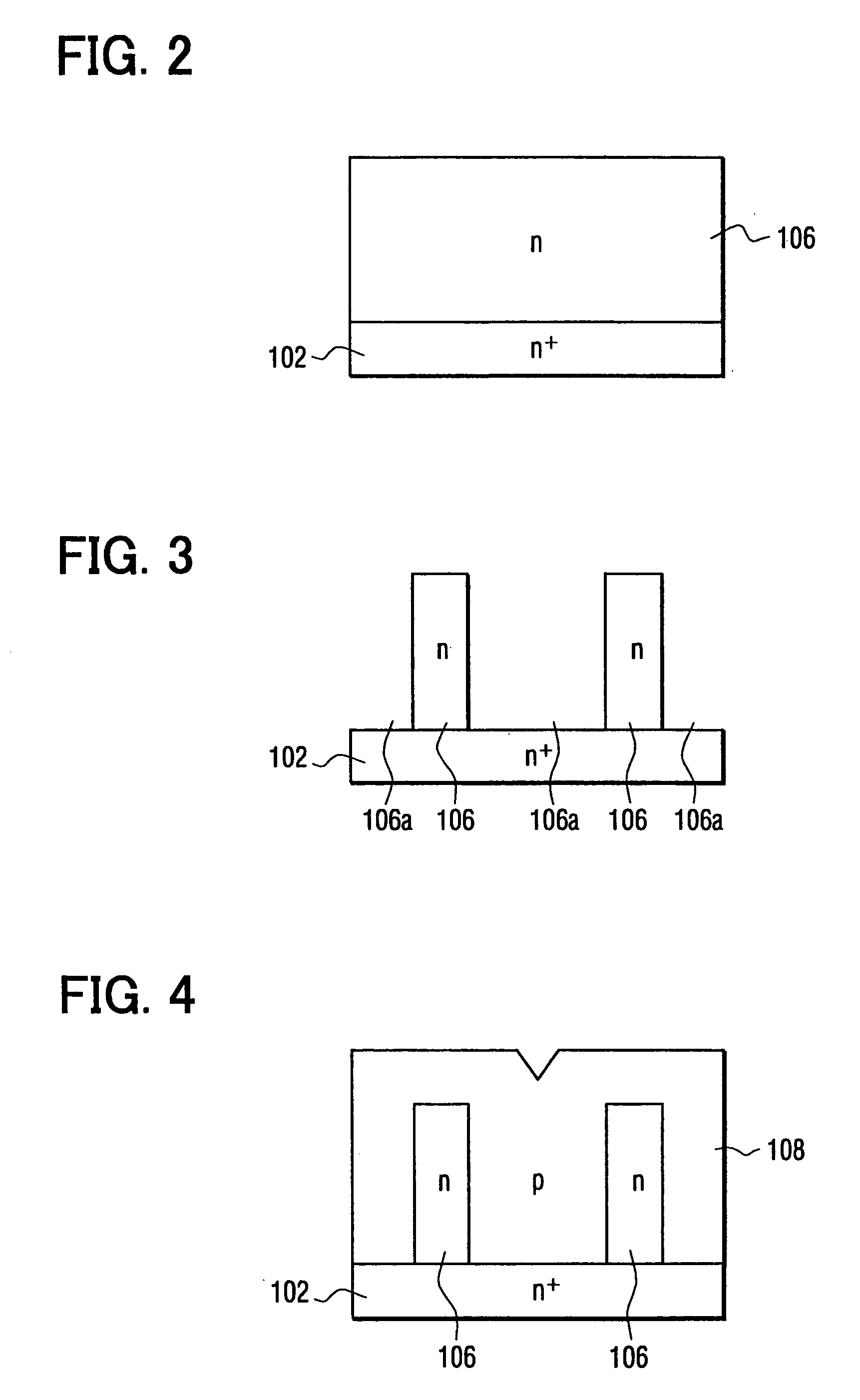
[0062]The drift region 106 is an n type (first conductivity type) and connects with the n+ type...
second embodiment
[0122]A vertical semiconductor device 200 as a second embodiment is shown in a sectional view in FIG. 29. The vertical semiconductor device 200 includes an n− type upper silicon region 210 independently from an n type drift region 206. The n− type upper silicon region 210 has an n type impurity of 1 E 16 cm−3, while the n type drift region 206 has an n type impurity of 2.8 E 16 cm−3. It is thus favorable that the n− type upper silicon region 210 has lower impurity concentration than the n type drift region 206. With an object that the n− type upper silicon region 210 should be occupied with the depletion layer during withstanding voltage, it is favorable that the n− type upper silicon region 210 has lower impurity concentration. By contrast, the n type drift region 206 is required to have low ON resistance in addition of high withstanding voltage, so that it favorably has high impurity concentration. The n− type upper silicon region 210 is assembled inside the p type body region 212...
third embodiment
[0129]A vertical semiconductor device 300 as a third embodiment is shown in a sectional view in FIG. 35. In the vertical semiconductor device 300, width (0.5 μm) of an n type drift region 306 is narrower than width (1 μm) of the n type drift region 106 of the first embodiment shown in FIG. 1. The n type drift region 306 has an n type impurity of 6.5 E 16 cm3. Width (3.5 μm) of a p type silicon region 308 is broader than width (3 μm) of the p type silicon region 108 of the first embodiment. The p type silicon region 308 has a p type impurity of 1.0 E 16 cm−3. Width (0.7 μm) of an n type upper silicon region 310 is narrower than width (3 μm) of the n type upper silicon region 110 of the first embodiment. Here, the n type upper silicon region 310 and the n type drift region 308 are formed as one uniform body with having a boundary at dotted line Y in FIG. 35.
[0130]Width (0.7 μm) of the n type upper silicon region 310 is narrower than that (1.2 μm) of a gate trench 313. The n type upper...
PUM
 Abstract
Description
Claims
Application Information
 - R&D
- Intellectual Property
- Life Sciences
- Materials
- Tech Scout
- Unparalleled Data Quality
- Higher Quality Content
- 60% Fewer Hallucinations
Browse by: Latest US Patents, China's latest patents, Technical Efficacy Thesaurus, Application Domain, Technology Topic, Popular Technical Reports.
© 2025 PatSnap. All rights reserved.Legal|Privacy policy|Modern Slavery Act Transparency Statement|Sitemap|About US| Contact US: help@patsnap.com


