Achromatic shearing phase sensor for generating images indicative of measure(s) of alignment between segments of a segmented telescope's mirrors

a technology of achromatic shearing phase and achromatic shearing, which is applied in the field of sensors, can solve the problems of limiting the capture range, affecting the measurement accuracy of edge sensors and their measurements, and not being well suited to long-term us

Inactive Publication Date: 2006-09-12
NASA +1
View PDF26 Cites 11 Cited by
  • Summary
  • Abstract
  • Description
  • Claims
  • Application Information

AI Technical Summary

Benefits of technology

[0021]Accordingly, it is an object of the present invention to provide a sensor that can be used in the alignment of a segmented telescope's mirrors.
[0022]Another object of the present invention is to provide a sensor that uses the interference of images generated by two adjacent segments of a segmented telescope in a simple manner.
[0023]Still another object of the present invention is to provide a sensor that provides information useful for aligning a segmented telescope in piston and tip / tilt.

Problems solved by technology

The difficulty in using a segmented telescope is that the mirror segments must be aligned such that they perform as a contiguous surface.
However, the physical size of the edge sensors and spacing therebetween limits the capture range thereof.
Further, edge sensors and their measurements can be affected by physical changes to the mirror segment's edges induced by environmental conditions.
Thus, edge sensors are not well suited to long-term use where the physical properties of a segmented telescope may change.
In general, phase diversity techniques are quite complex and time consuming making them impractical for use with dynamic telescopes or telescopes that drift at a faster rate than the time it takes for the phase diversity calculation to be completed.
Phase retrieval techniques are also somewhat limited in that they generally must be used with point sources, although an extended source could be used if sufficient spatial information is provided.
However, use with a broadband source requires a substantial amount of sensing and processing sophistication.
While the curvature sensing technique utilizes a fast algorithm for analyzing the piston errors of a segmented telescope, it is an iterative process and has a limited capture range.
However, image metric techniques can only optimize alignment with regard to the particular metric being employed which, typically, is only indicative of one aspect of alignment.
Thus, image metric techniques may not provide the necessary information for overall mirror segment alignment.
However, the algorithm used for narrowband phasing is limited in its accuracy.
The accuracy of the DFS technique reduces as the piston difference approaches zero and the period of the overall pattern becomes large or infinite.
More importantly, both of the above-described mask-based sensors (i.e., PCS and DFS) are limited to measuring very small edge portions of each mirror segment.

Method used


Image

  • Achromatic shearing phase sensor for generating images indicative of measure(s) of alignment between segments of a segmented telescope's mirrors
  • Achromatic shearing phase sensor for generating images indicative of measure(s) of alignment between segments of a segmented telescope's mirrors
  • Achromatic shearing phase sensor for generating images indicative of measure(s) of alignment between segments of a segmented telescope's mirrors

Examples


Embodiment Construction

)

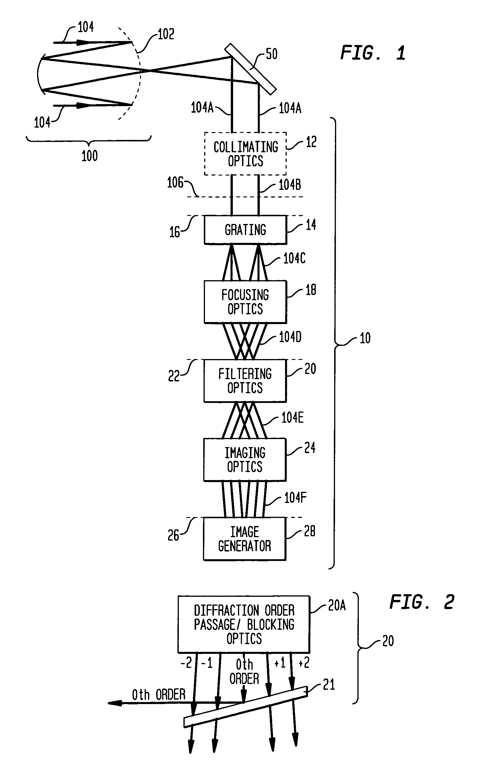
[0034]Referring now to the drawings, and more particularly to FIG. 1, an embodiment of an achromatic shearing phase sensor according to the present invention is shown and is and referenced generally by numeral 10. Sensor 10 will be described herein for use with a telescope 100 of any known type in the art that has a primary mirror divided into a plurality of mirror segments 102 that receive incoming irradiance 104 from a source (not shown) as is known in the art. Mirror segments 102 focus irradiance 104 at a location where an end user can view the focused image. For purpose of the present invention, a portion of irradiance 104 will be used by sensor 10 to generate an image that is indicative of one or more measures of alignment between two adjacent mirror segments.

[0035]Mirror segments 102 require initial alignment and alignment from time-to-time during the life of telescope 100. In general, sensor 10 generates an image associated with large portions of two mirror segments. However...


PUM


Abstract

An achromatic shearing phase sensor generates an image indicative of at least one measure of alignment between two segments of a segmented telescope's mirrors. An optical grating receives at least a portion of irradiance originating at the segmented telescope in the form of a collimated beam and the collimated beam into a plurality of diffraction orders. Focusing optics separate and focus the diffraction orders. Filtering optics then filter the diffraction orders to generate a resultant set of diffraction orders that are modified. Imaging optics combine portions of the resultant set of diffraction orders to generate an interference pattern that is ultimately imaged by an imager.

Description

[0001]This application claims the benefit of provisional application 60 / 474,753 filed May 29, 2003.ORIGIN OF THE INVENTION[0002]The invention was made in performance of work under a NASA contract and by an employee of the United States Government and is subject to the provisions of Public Law 96-517 (35 U.S.C. §202) and may be manufactured and used by or for the Government of the United States of America for governmental purposes without the payment of any royalties thereon or therefor. In accordance with 35 U.S.C. §202, the Contractor has elected not to retain title. Pursuant to 35 U.S.C. §119, the benefit of priority from provisional application 60 / 474,753, with a filing date of May 29, 2003, is claimed for this non-provisional application.BACKGROUND OF THE INVENTION[0003]1. Field of the Invention[0004]This invention relates to sensors used to align mirror segments of a segmented telescope. More specifically, the invention is an achromatic shearing phase sensor that can be used in...

Claims


Application Information

Patent Timeline
IPC IPC(8): G01B9/02
CPCG01B11/272G02B27/62G01J9/0215G01J2009/0296
Inventor STAHL, H. PHILIPWALKER, CHANDA BARTLETT
Owner NASA
Why Eureka
Try Eureka