Capacitive occupant sensor for a vehicle seat

a technology for occupant sensors and vehicle seats, applied in the field of capacitance sensors, can solve the problems of disturbing the relationship between capacitance change and applied force, and the area of the bladder that is able to expand,

Inactive Publication Date: 2006-09-12
DELPHI TECH INC
View PDF12 Cites 13 Cited by
  • Summary
  • Abstract
  • Description
  • Claims
  • Application Information

AI Technical Summary

Problems solved by technology

However, as the area over which the occupant force is applied increases, the area of the bladder that is able to expand decreases, disturbing the relationship between capacitance change and applied force.

Method used


Image

  • Capacitive occupant sensor for a vehicle seat
  • Capacitive occupant sensor for a vehicle seat
  • Capacitive occupant sensor for a vehicle seat

Examples


Embodiment Construction

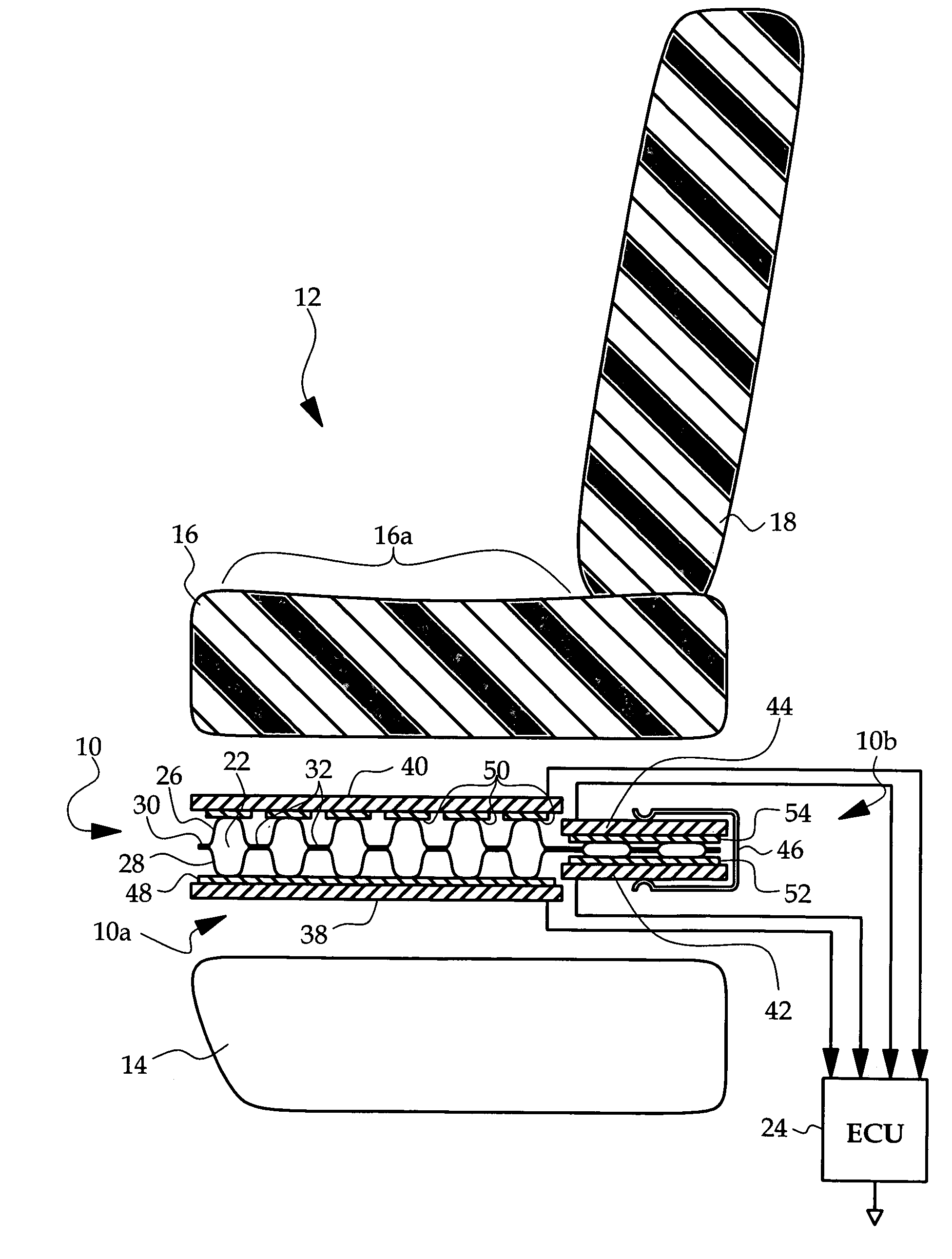
[0011]Referring to FIG. 1, the reference numeral 10 generally designates the capacitive occupant sensor of this invention in the context of a vehicle seat 12 comprising a seat frame 14, a foam seat cushion 16 and a foam back cushion 18. The sensor 10 includes a primary region 10a and a secondary region 10b. The primary region 10a is disposed between the seat frame 14 and the seating surface 16a of seat cushion 16 so that occupant-related forces applied to the seating surface 16a are transmitted to primary region 10a through the seat cushion 16. One the other hand, the secondary region 10b is positioned such that it is shielded from forces applied to the seating surface 16a. In the illustration, this is achieved by locating the secondary region 10b under the back cushion 18; a more detailed discussion of various locations of the secondary region 10b is presented below in reference to FIGS. 3A–3B.

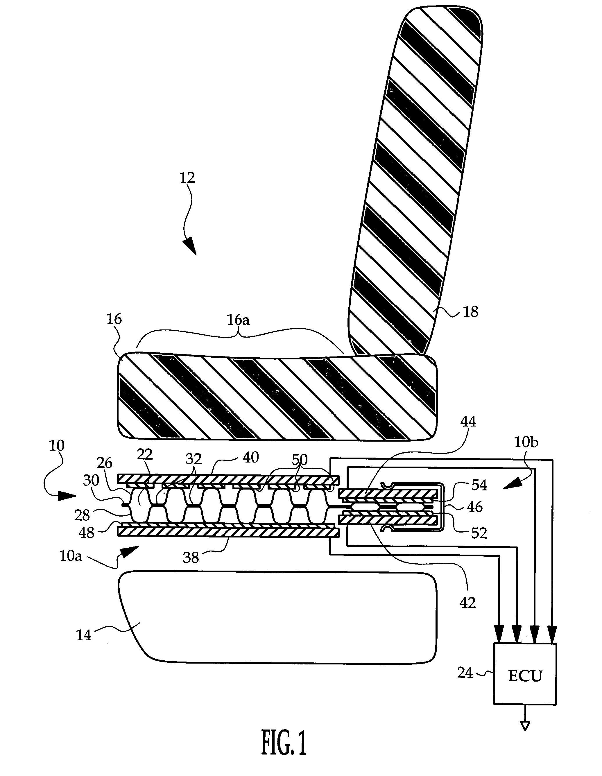
[0012]In general, the sensor 10 comprises various conductor plates oppositely disposed ab...


PUM


Abstract

A capacitive occupant sensor for a seat has a dielectric in the form of a fluid-filled elastomeric bladder, and the sensor includes a primary region that is subjected to occupant force and a secondary region that is shielded from occupant force. The secondary region includes an appendage of the bladder that is disposed beneath a back cushion of the seat, either in a cavity of the seat cushion or below a frame element that supports the seat cushion. A spring clamp normally biases fluid out of the appendage, but occupant-related force applied over a broad area of the seat produces a flow of bladder fluid into the appendage against the bias force of the spring clamp. A pair of auxiliary conductor plates is oppositely disposed about the bladder appendage, and the capacitance between the auxiliary conductor plates is measured as an indication of fluid pressure in the bladder.

Description

RELATED APPLICATIONS[0001]This application is a continuation-in-part of U.S. Patent application Ser. No. 10 / 643,044, filed Aug. 18, 2003 now U.S. Pat. No. 6,927,678.TECHNICAL FIELD[0002]The present invention is directed to a capacitive sensor including a fluid-filled bladder responsive to occupant-related force applied to a vehicle seat.BACKGROUND OF THE INVENTION[0003]Occupant detection and classification are frequently used in connection with air bags and other pyrotechnically deployed restraints for purposes of determining if the restraints should be deployed in the event of sufficiently severe crash. Various vehicle seat sensors have been devised for this purpose, such as disclosed, for example, in the U.S. Pat. Nos. 5,987,370 and 6,246,936 to Murphy et al., and the U.S. Pat. Nos. 6,101,436 and 6,490,936 to Fortune et al., all of which are assigned to Delphi Technologies, Inc., and incorporated herein by reference. In general, occupant presence can be detected based on the overa...

Claims


Application Information

Patent Timeline
Patent Type & Authority Patents(United States)
IPC IPC(8): G08B21/00B60NB60N2/00B60Q1/00B60R21/015G05D1/00
CPCB60N2/002G01G7/06B60R21/01516B60R21/01532G01G19/4142
Inventor SPRECHER, PHILLIP B.FULTZ, WILLIAM W.
Owner DELPHI TECH INC
Why Eureka
Try Eureka