
Glass ceramic or glass cook top with an IR-permeable undercoat

Inactive Publication Date: 2006-09-12
SCHOTT AG
View PDF29 Cites 8 Cited by
  • Summary
  • Abstract
  • Description
  • Claims
  • Application Information

AI Technical Summary

Benefits of technology

[0017]Because the coating according to the invention is made from inorganic enamel paint it is permanently stable up to about 600° C. It is not possible however to use conventional inorganic enamel paint, since the paint either does not block observation through the cook top or the strength or durability of the glass ceramic cook top is undesirably greatly reduced. A coating with the desired properties according to the object of the invention can be obtained surprisingly by a modification of the enamel paint, when the proportion of the glass flux is reduced to only 1 to 30 percent by weight and the proportion of inorganic pigment amounts to 70 to 99 percent by weight. A view-blocking or observation-preventing coating is obtained with this composition because of the high pigment content. Because of the small portion of glass flux the strength or durability of the glass ceramic cook top is only slightly reduced.

Problems solved by technology

The appearance of these structural elements is considered to be troublesome for the user.
However the application of a observation-preventing coating is costly, especially when it occurs by means of screen printing, as in the case of DE 199 06 737 A1.
The disadvantage of these organic paints is that they have only limited heat-resistance because of their organic composition.
Typical ingredients, such as silicones, polyesters or resins, decompose at temperatures above 400° C. However in operation the underside of the cook top of cooking ranges reaches up to 600° C. The organic paints decompose generally under heat load and the adherence of the coating is lost over time.
However the strength of the glass ceramic cook top is clearly reduced because of differing thermal expansion coefficients and the mechanical stresses thereby produced.
Furthermore the resulting coating is not observation preventing or view blocking.

Method used


Image

  • Glass ceramic or glass cook top with an IR-permeable undercoat
  • Glass ceramic or glass cook top with an IR-permeable undercoat

Examples


Embodiment Construction

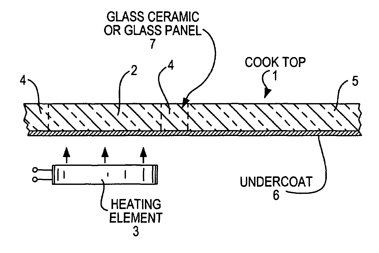
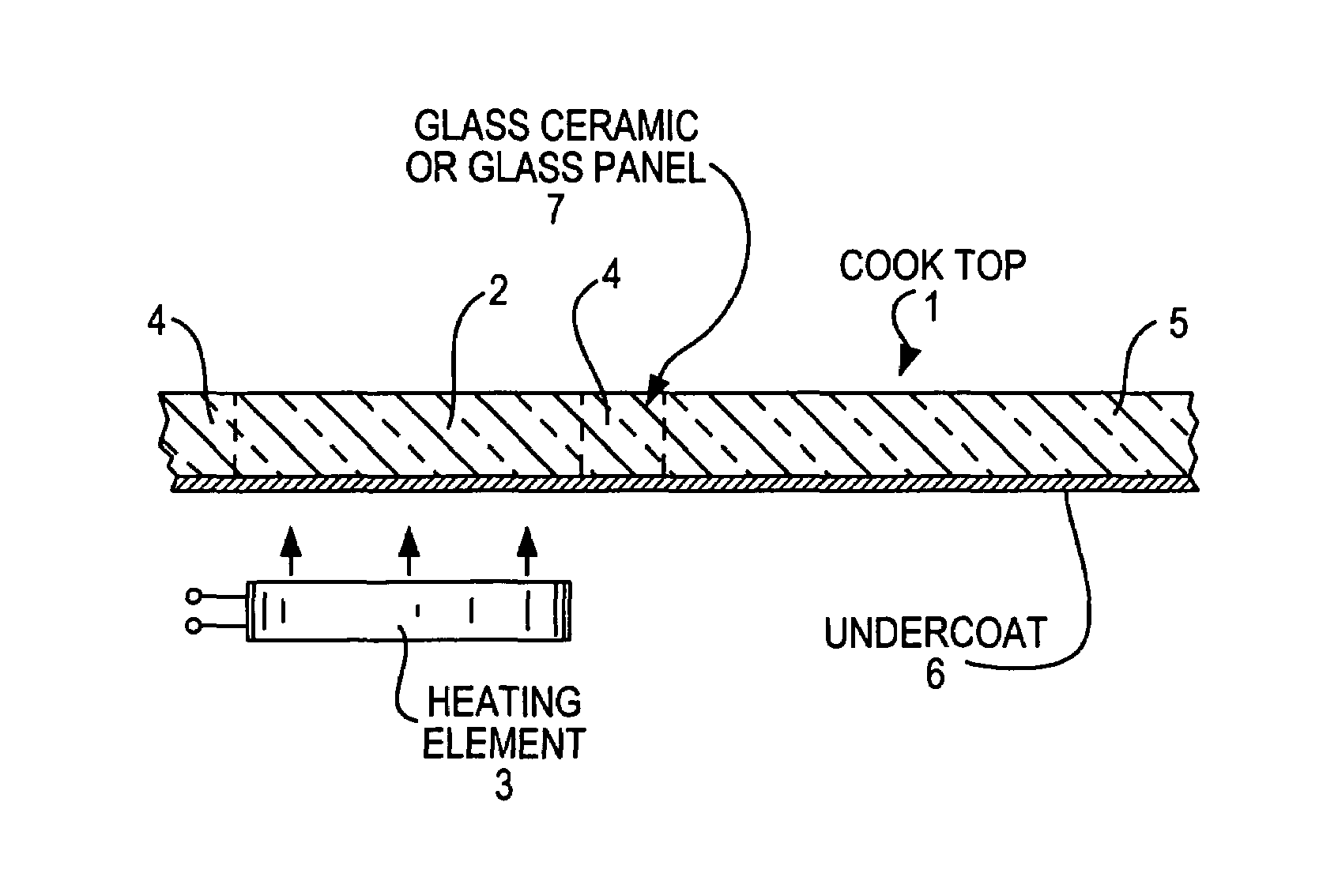
[0026]The glass ceramic cook top 1 has at least one cooking zone 2 marked with the dashed vertical lines, i.e. a heated region, which is associated with an electrically operated radiant heating element 3. The heated region typically has a temperature of greater than about 350° C. It is surrounded by a ring-shaped or annular transition zone 4 marked with dashed lines with a width of 0 to 25 mm and a cool region 5, in which the temperature is usually maintained under about 220° C.

[0027]The cook top 1 comprises a transparent, colorless glass ceramic panel 7 providing the cooking surface and an undercoat 6 on its under side. The continuous, preferably full-surface, undercoat 6 is made from inorganic enamel paint according to the invention, which is applied to the underside of the transparent colorless glass ceramic panel 7.

[0028]This continuous undercoat 6 is applied during production in the simplest manner, e.g. by screen printing. However it would be sufficient in principle to coat on...


PUM

PropertyMeasurementUnit
Percent by massaaaaaaaaaa

Abstract

The cook top has a transparent, colorless glass ceramic or glass panel providing a cooking surface, which is made from pre-stressed special glass, and an IR-permeable undercoat on the underside of the panel, which is a heat-resistant inorganic enamel paint. In order to provide a heat-resistant cook top, through which the internal parts of the cooking unit cannot be observed, without reducing the strength of the cook top, the inorganic enamel paint includes 70 to 99, preferably 80 to 95, percent by weight of inorganic pigment and from 1 to 30, preferably 5 to 20, percent by weight of glass flux. The glass flux preferably is a borosilicate glass with a thermal expansion coefficient less than or equal to 4*10−6 K−1. The coating may be applied by screen printing techniques.

Description

BACKGROUND OF THE INVENTION[0001]1. Field of the Invention[0002]The present invention relates to glass ceramic cook top or glass cook top comprising a glass ceramic or glass panel made of pre-stressed special glass, which provides a cooking surface, and an IR-permeable coating made of a heat-resistant inorganic enamel paint, which comprises an inorganic pigment and a glass flux, on the underside of the glass ceramic or glass panel.[0003]2. Description of the Related Art[0004]Cooking ranges with glass or glass ceramic panels acting as cook tops are commercially available in the art. Glass cook tops are typically transparent for visible light, however glass ceramic cook tops are usually translucent. When illuminated from above, e.g. by the cooking unit lighting, or from below, by heat radiation, the heating elements, cables and other structural components, which are hidden below the glass ceramic cooking area, can be observed and show through it. The appearance of these structural ele...

Claims


Application Information

Patent Timeline
IPC IPC(8): B32B17/00A47B96/18C03C17/00C03C17/04F24C15/10H05B3/74H05B6/12
CPCC03C17/007C03C17/04H05B3/74C03C2217/485C03C2217/452
Inventor STRIEGLER, HARALD
Owner SCHOTT AG
Learn More