Method and apparatus for reconditioning compact discs

a compact disc and reconditioning technology, applied in the field of compact discs, can solve problems such as disturbances in faulty reproduction, tracking errors or distortions, and damage to the information layer

Inactive Publication Date: 2006-09-12
KENNEDY MICHAEL S
View PDF19 Cites 17 Cited by
  • Summary
  • Abstract
  • Description
  • Claims
  • Application Information

AI Technical Summary

Benefits of technology

[0014]Re-surfacing is first accomplished in an apparatus having a cabinet in which is mounted a pair of motors having spindles or shafts vertically extending in spaced parallel relationship. The spindles or shafts are rotated in opposite directions, one being rotated clockwise and the other being rotated counter-clockwise. The shafts extend upwardly into a re-surfacing chamber in the cabinet. Each of the shafts extend through a fixed protective sleeve. An arbor is secured to the end of one of the shafts and a resilient foam pad is detachably secured to the arbor by an adhesive or a loop and hook fastener material such as that sold under the trademark Velcro®. A circular pad having an abrasive surface is secured to the upper surface of the foam pad with the abrasive surface facing upwardly. The adjacent, oppositely rotating shaft has a protective

Problems solved by technology

Damage to the information layer can occur if scratches or other surface blemishes occur in the plastic protective layer.
Damage, as mentioned, to the protective layer will interfere with the scanning process such that tracking errors or distortion will occur when the disc is played.
Even relatively small scratches or blemishes resulting from handling of the disc can lead to disturbances in faulty reproduction.
The laser reading beam scans the data track and blemishes, imperfections and scratches in the protective layer which is generally a polycarbonate, will hinder the laser's ability to properly read the data and “skips” will occur.

Method used


Image

  • Method and apparatus for reconditioning compact discs
  • Method and apparatus for reconditioning compact discs
  • Method and apparatus for reconditioning compact discs

Examples


Embodiment Construction

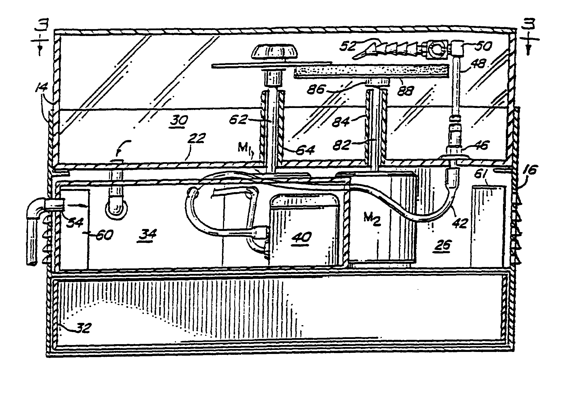
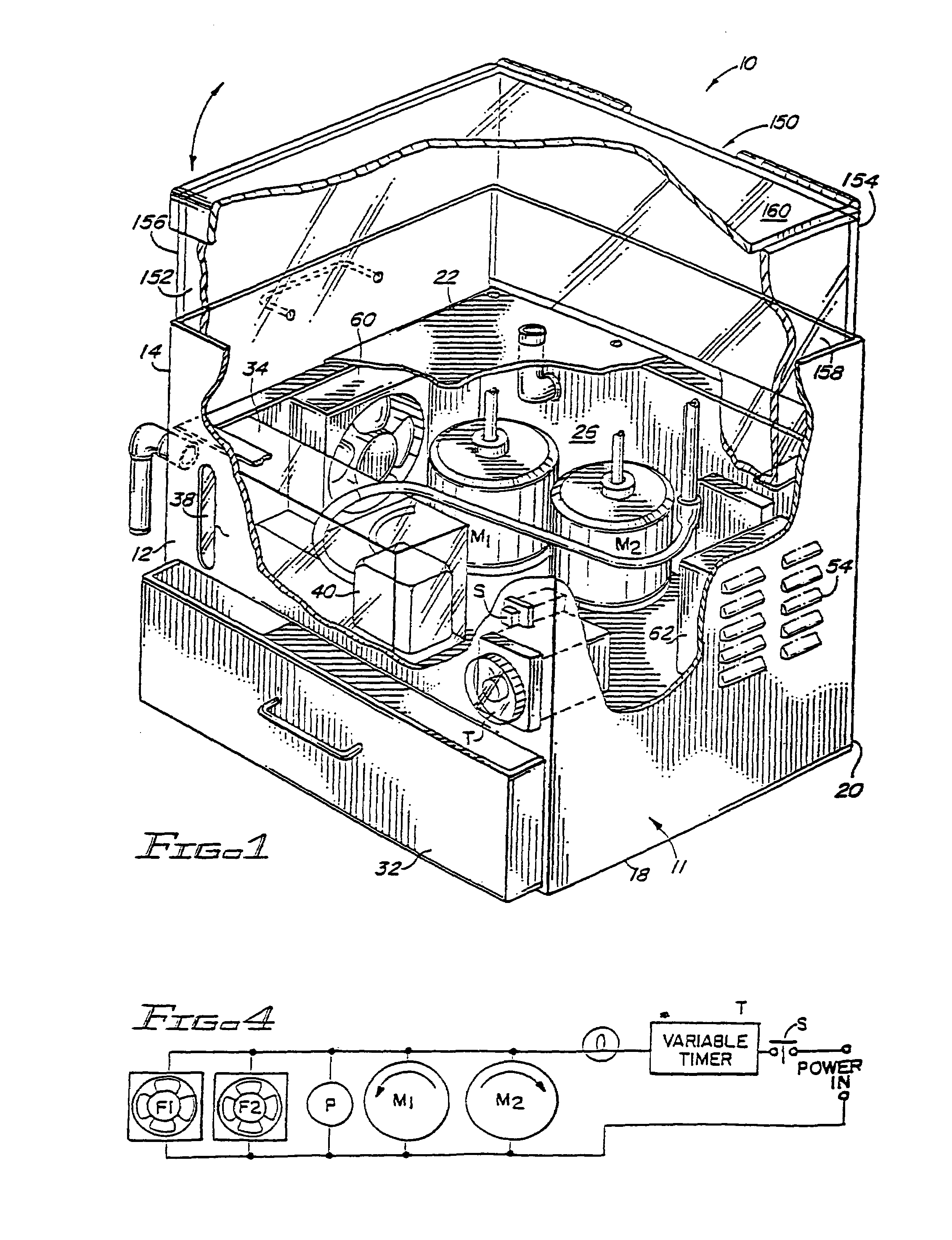
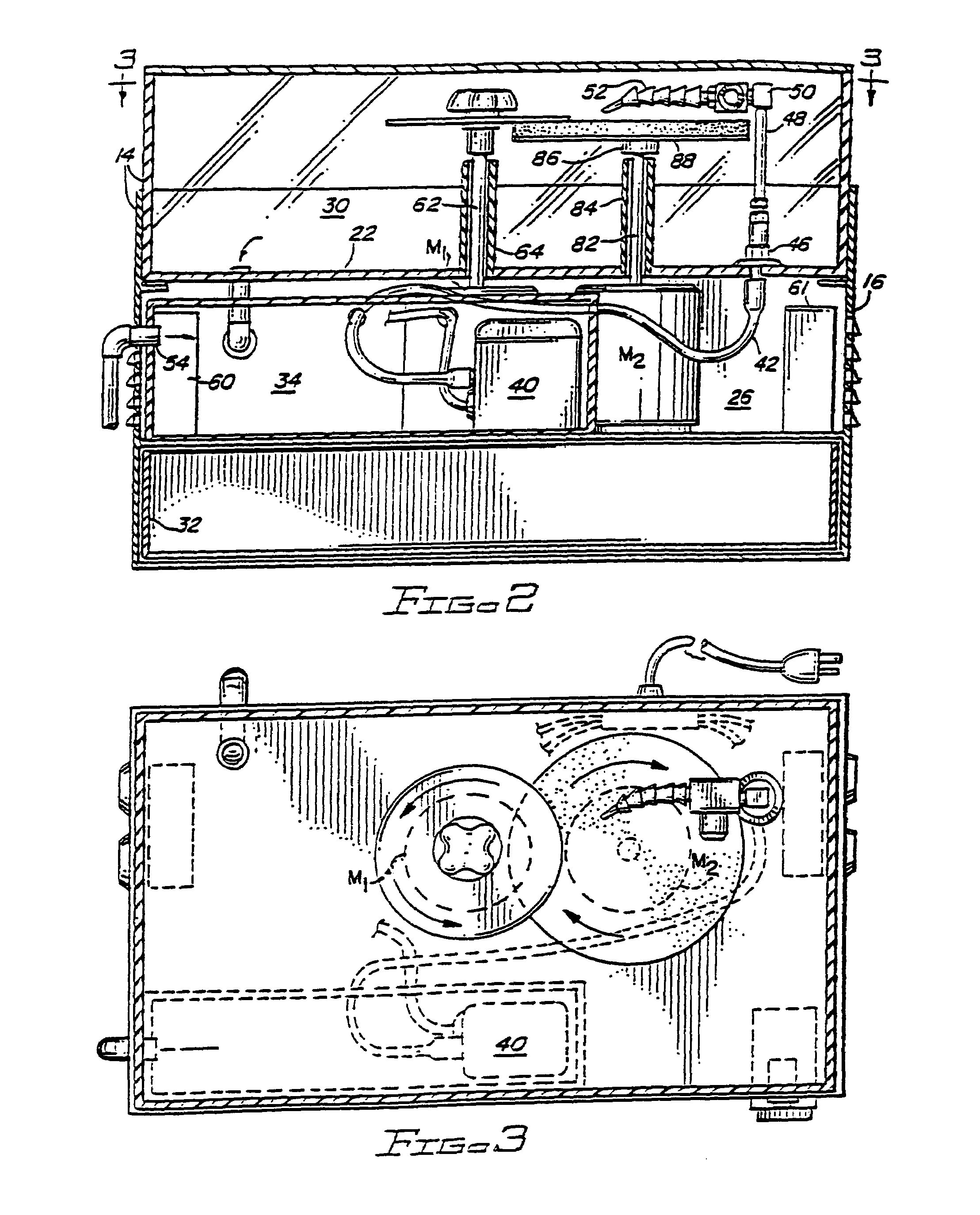
[0030]The present invention provides both an apparatus and method for re-conditioning compact discs and other discs containing digital information such as DVD's and game discs and the terms “disc” or “CD” are used herein to apply to a variety of information bearing discs fo this type including, but not limited to, CD's, DVD's, computer discs and game discs. The method involves first removing the deeper scratches and blemishes in a first re-surfacing apparatus of the type shown in FIGS. 1 to 4. Subsequently, the plastic surface of the discs, from which the deeper blemishes and scratches have been removed, are polished on a polishing apparatus such as shown in FIGS. 7 and 8. The apparatuses shown in FIGS. 1 to 4 and FIGS. 7 and 10 utilize a first rotatable shaft on which the CD to be processed is mounted and a second, spaced-apart parallel shaft which has an arbor on which the polishing pad or abrasive material is mounted. The two shafts are rotated in opposite directions toward one a...


PUM

PropertyMeasurementUnit
Lengthaaaaaaaaaa
Forceaaaaaaaaaa
Speedaaaaaaaaaa

Abstract

An apparatus and method for re-surfacing compact discs. One method is a two-step method in which the disc to be re-surfaced is first placed on a shaft. A resilient pad supports an abrasive medium and is positioned so the abrasive medium overlaps only the protective layer of the CD. The disc and abrasive material are rotated in opposite directions at about the same speed to remove deeper blemishes in a wet operation. Subsequent polishing is accomplished in a similar manner using a polishing compound instead of an abrasive. The re-surfacing and polishing apparatus each have motor driven shafts which are parallel and spaced apart and support the CD and pad in a cabinet. A transparent cover extends across the top of the cabinet. In another embodiment, the resurfacing and polishing is accomplished in a one-step operation in which polishing fluid is applied to a non-abrasive medium is utilized and the fluid is continuously recycled.

Description

CROSS-REFERENCE TO RELATED APPLICATIONS[0001]This a continuation-in-part of U.S. application Ser. No. 09 / 990,152, filed Nov. 21, 2001, now U.S. Pat. No. 6,780,090 which is a divisional of U.S. application Ser. No. 09 / 449,153 filed Nov. 24, 1999, now U.S. Pat. No. 6,322,430 which is a continuation-in-part of U.S. application Ser. No. 08 / 879,711 filed Jun. 20, 1997, now abandoned all entitled “Method And Apparatus For Reconditioning Compact Discs”FIELD OF THE INVENTION[0002]The present invention relates to compact discs and more particularly relates to an apparatus and method of reconditioning both audio and compact discs by removing scratches and blemishes in the protective plastic layer on one side of the disc which occur through use and handling of the discs.BACKGROUND OF THE INVENTION[0003]Compact discs (CD's) are widely used for storing both audio and visual information in digital form. Compact discs are discs which consist of a disc of plastic having a thickness of about 1 mm to...

Claims


Application Information

Patent Timeline
IPC IPC(8): B24B1/00B24B29/00
CPCB24B37/04B24B57/02G11B23/505B29B17/02B29L2017/005Y02W30/62
Inventor KENNEDY, MICHAEL S.
Owner KENNEDY MICHAEL S
Why Eureka
Try Eureka