
Memory card shaped card reader

a memory card and card reader technology, applied in the field of memory card shaped card readers, can solve the problems of inconvenient use, high cost of card readers, bulky, etc., and achieve the effects of simple manufacturing process and circuitry, reduced size, and low manufacturing cos

Inactive Publication Date: 2006-09-12
DATAFAB SYST
View PDF5 Cites 109 Cited by
  • Summary
  • Abstract
  • Description
  • Claims
  • Application Information

AI Technical Summary

Benefits of technology

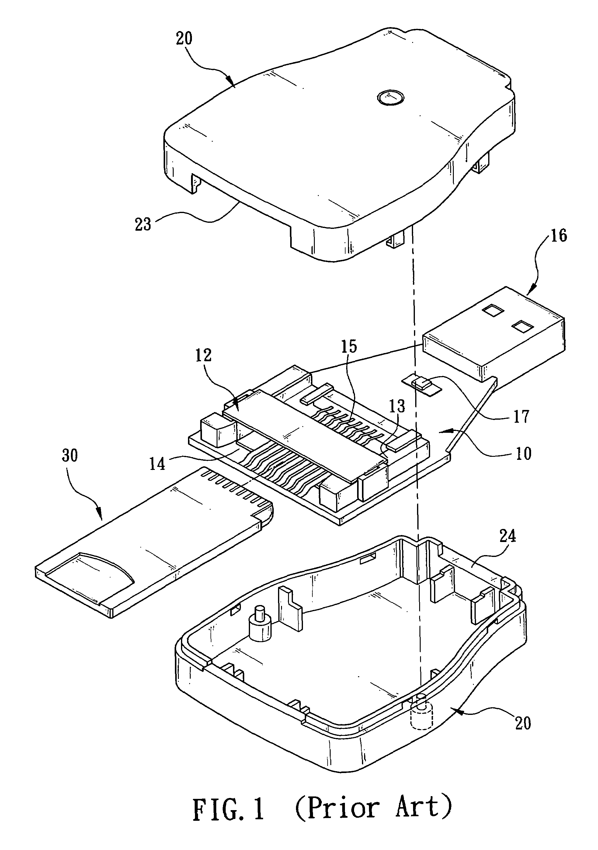
[0006]After considerable research and experimentation, a memory card shaped card reader having a low manufacturing cost, simple manufacturing processes and circuitry, greatly reduced size, and features of both card reader and adapter according to the present invention has been devised so as to overcome the above drawbacks (e.g., complicated mechanism, high cost, and bulkiness) of the prior card reader.

Problems solved by technology

However, the user is not able to either operate an electronic product to read data from a memory card having different specifications inserted into the insertion slot of the electronic product or operate a notebook computer to read data from a memory card having different specifications inserted into the USB connector of the notebook computer.
Inevitably, users have to spend more money on buying these devices (i.e., bear a great financial burden upon users) and it is very inconvenient in use.
However, this type of card reader is expensive, bulky, and not easy to carry.
It is thus a waste for a user to buy such unpractical card reader since the user may never have a chance to use certain or even many insertion slots of the card reader to read data from inserted memory cards.

Method used


Image

  • Memory card shaped card reader
  • Memory card shaped card reader
  • Memory card shaped card reader

Examples


Embodiment Construction

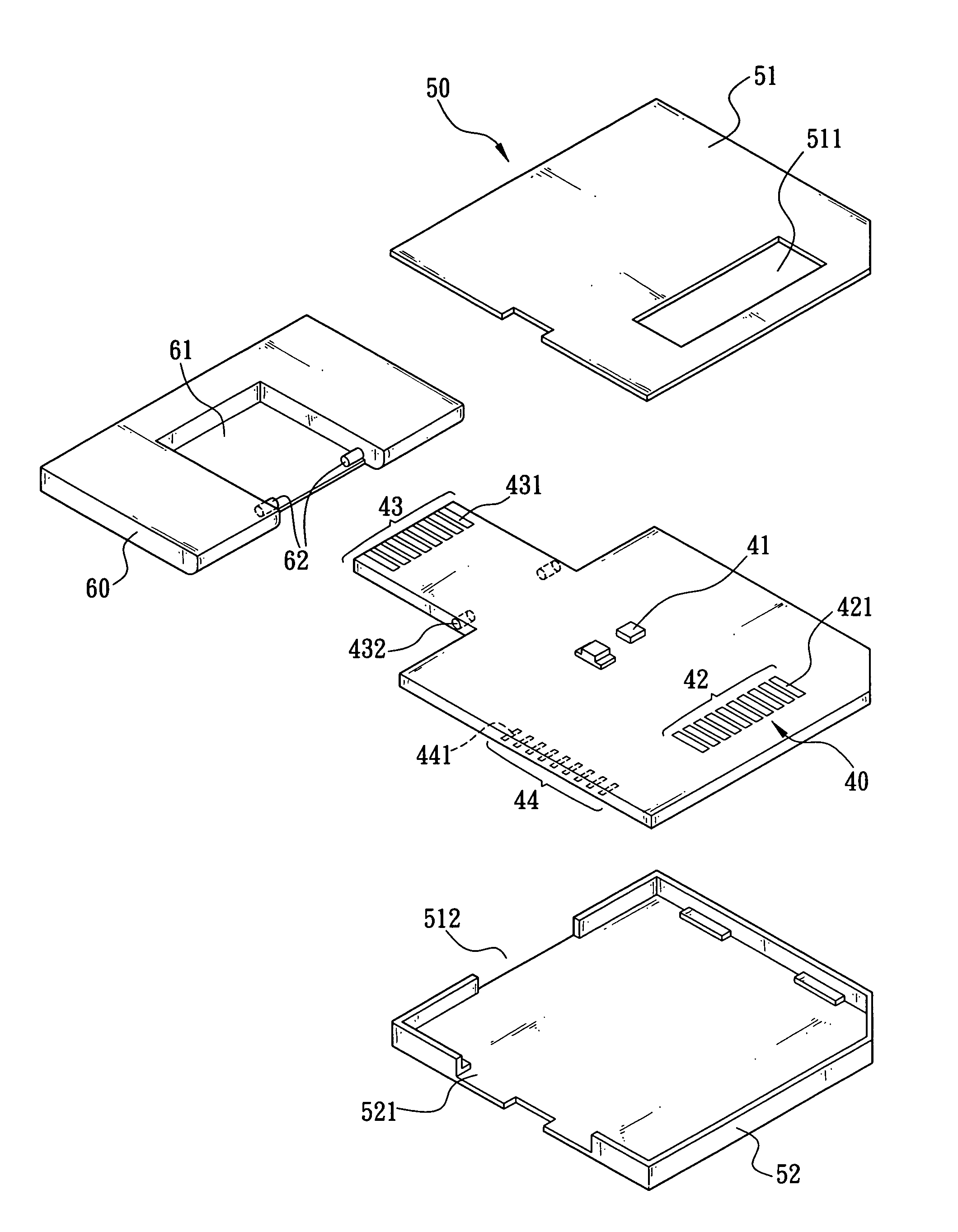
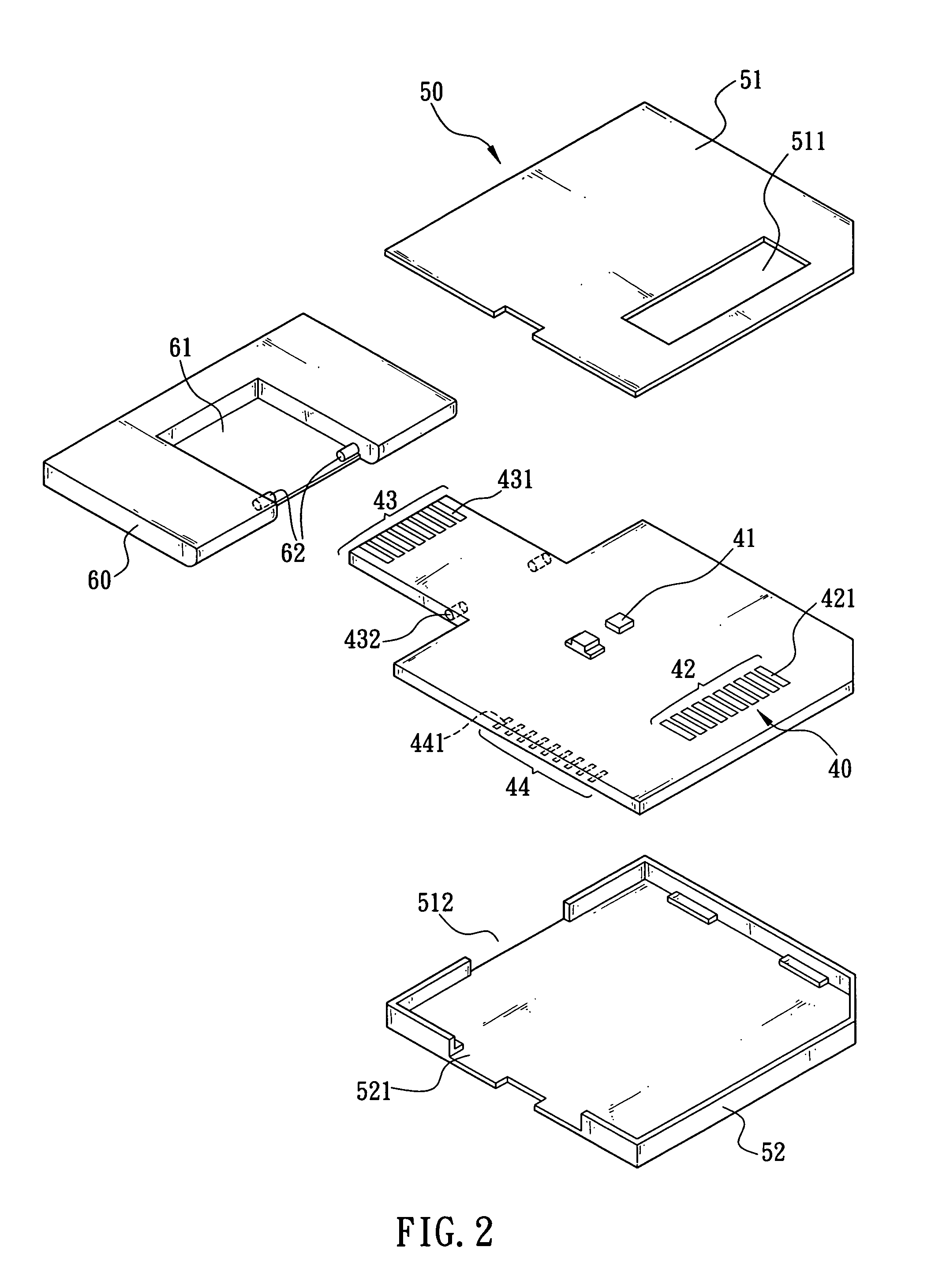
[0018]Referring to FIG. 2, a memory card shaped card reader in accordance with a first preferred embodiment of the invention comprises a circuit board 40 having required circuitry (not shown) and a controller 41 such that the card reader can be additionally configured as an adapter for memory card. A plurality of parallel contacts 421 are fixedly mounted on a specific position on the circuit board 40 proximate one end thereof by surface mounting. The contacts 421 are collectively formed as a first external connector 42 complied with the specifications of a first type of memory card (e.g., Memory Stick available from SONY Corporation having dimensions of 21.5×50.0×2.8 mm or SD having dimensions of 24×32×2.1 mm). Also, a plurality of parallel contacts 431 are fixedly mounted on another specific position on the circuit board 40 at the other opposite end thereof by surface mounting. The contacts 431 are collectively formed as a second external connector 43 complied with the specificatio...


PUM


Abstract

The present invention is to provide a circuit board in a housing and a plurality of contacts fixedly mounted on each of one end, the other end, and at least one side of the circuit board by surface mounting for forming a first external connector, a second external connector, and at least one internal connector wherein each of the first and the second external connectors is exposed to be ready for connection, at least one insertion slot is formed in the housing and, in response to inserting a memory card (e.g., T-Flash Card) into the insertion slot, a plurality of contacts of the internal connector are electrically connected to a plurality of conductive terminals of the memory card. Further, a shield is pivotally formed at the second external connector projected from the other end of the circuit board wherein the shield and the housing are assembled together to have a size dimensioned to comply with the specifications of a first type of memory card (e.g., Memory Stick Card or SD Card).

Description

FIELD OF THE INVENTION[0001]The present invention relates to card readers and more particularly to a memory card shaped card reader complying with the specifications of a first type of memory card (e.g., Memory Stick Card or SD Card) and capable of being inserted with a second type of memory card (e.g., T-Flash Card) as an adapter of the second type of memory card for inserting into one insertion slot complying with the specifications of a first type of memory card.BACKGROUND OF THE INVENTION[0002]Various memory cards having different specifications are commercially available. Memory cards can be classified as large memory cards and small memory cards based on size. Large memory cards comprise MMC (MultiMediaCard), CF (CompactFlash™ Card), SD (Secure Digital), SM (Smart Media), and MS (Memory Stick) available from SONY Corporation. MMCs, CFs, and SDs not only have large market shares but also are widely used as main memory cards in DSCs (Digital Still Cameras), MP3 players, and othe...

Claims


Application Information

Patent Timeline
IPC IPC(8): H01R12/00
CPCG06K19/077G06K19/07732G06K19/07733H01R27/00H01R31/06G06K19/07741Y10S439/951H01R12/721
Inventor HUANG, DER-SHENG
Owner DATAFAB SYST
Learn More