
Saddle

Inactive Publication Date: 2006-09-12
SCHOLZ HANS
View PDF19 Cites 52 Cited by
  • Summary
  • Abstract
  • Description
  • Claims
  • Application Information

AI Technical Summary

Benefits of technology

[0010]Proceeding from the initially described saddle with two seat halves which are spaced apart from one another and which are each designed for one half of the buttocks, a primary object of the invention is to provide such a saddle which ensures use essentially free of pressure points with optimum transfer of force to the pedals and simultaneously a solid seat.
[0015]When using the saddle of the invention, therefore in its mounted state, it is furthermore preferred that the cup joint axes are also forwardly inclined. Thus, as a result, less tilting of the two seat halves to the rear than to the front is enabled. It is especially possible in this way not to allow tilting of the two seat halves to the rear beyond the horizontal. That the cup joint axes are tilted to the front, for, example, can be achieved by a correspondingly made support rod. However, the mounting of the support rod on the saddle support must also be considered, currently available saddle supports generally enabling adjustment of the tilt range of the support rod and thus of the saddle to the front or back.
[0016]Basically, it is possible to achieve a range of motion of the cup element in the socket of the respective cup joint arrangement in different ways. According to one preferred development of the invention, it is provided that the means for limiting the range of motion of the cup element in the socket the cup element has a collar on its top end and / or on its bottom end which strikes the edge of the socket at the end of the range of motion. In this way, the angle within which the cup element can be moved in the socket can be exactly predetermined. If there is a collar both on the top edge and also on the bottom edge of the cup element, it is a double collar cup joint which is located in an annular socket.
[0017]According to a preferred embodiment of the invention, it is especially provided that the edge of the socket and the collar of the cup element, which collar at the end of the range of motion strikes the edge of the socket, are matched to one another such that extended resting of the collar of the cup element on the edge of the socket occurs. Specifically, this means that the collar of the cup element and the edge of the socket which interact with it are angularly matched to one another so that, not only do the two elements rest on one another at one point, but they at least rest along a line. In this way, the forces which act between the cup element and the socket are better distributed; this reduces wear of the cup joint arrangement overall. Moreover, the collars are especially well suited as guide elements for the motion of the cup joint. Essentially, sliding motion of the collars on the edge of the annular socket is enabled; the stop can act as a sliding stop.
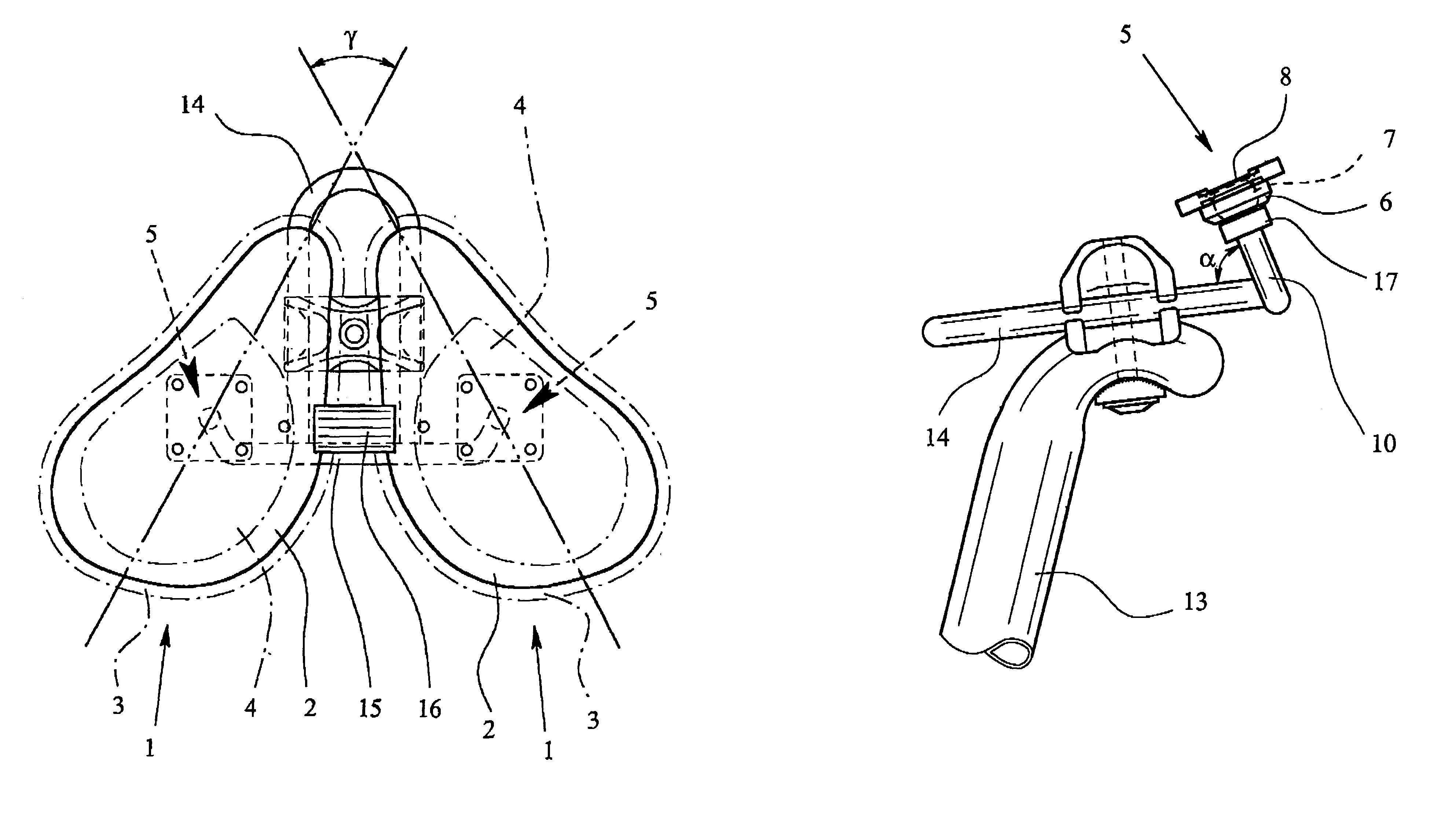
[0021]Furthermore, it has been found to be advantageous that the respective cup joint is provided under the center of gravity of the respective seat half. Moreover, the cup joint axes preferably lie in one plane. While the supports are typically made the same length, it can also be provided that the supports are of different length in order to compensate, for example, for malpositions of the pelvis.
[0022]The shape of the two seat halves also acquires great importance. While basically round or oval seat halves can be used, according to a preferred embodiment of the invention, it is provided that the seat halves each have the shape of a half heart with a short and rounded tip which points forward. Furthermore, here it applies that, preferably, the major axes include an angle which is in the range between 50° and 65°, preferably 57°, along the respectively greatest extension of each seat half. The major axes along the respective greatest extension of each seat half typically run through the end of the tip and the center of gravity of the seat half. In this way, the saddle shape enables optimum leg guidance and ergonomic pedaling. According to a preferred development of the invention, it is furthermore provided that the facing edges of the two seat halves run roughly parallel to one another, specifically preferably, as indicated above, at a distance of roughly 2 cm or somewhat less.

Problems solved by technology

For this reason, the force expended by the rider, specifically his body and muscle force, is not optimally converted into the given circular rotation of the pedals.
The friction of the upper leg on the saddle edge, the pressure load on the buttocks, overshooting of the leg motion—the knee and hip joints execute a more “S”-shaped than round motion relative to the pedal axis—as well as rocking of the upper body of the rider back and forth, in sum, cause a waste of the expended force so that, overall, an uneconomical sequence of motions is achieved.
Add to this, the discomfort caused by pressure points for the rider, which moreover can lead to health impairment and health damage.
In spite of the use of padding, such as gel cushions, circulation problems of the genitals, inflammations of the urinary tract, microtrauma of the testes or prostate up to infertility and impotence have been reported.
The aforementioned problems cannot be avoided with them.
Thus, it is a problem in this known saddle that the possible motions of the two seat halves cannot follow the biomechanically most favorable motions of the legs, pelvis, and upper body when bicycling.
However, the saddle described in German Utility Model DE 201 00 412 U1 does not enable a solid and comfortable seat so that it has not become popular in practice.

Method used


Image

  • Saddle
  • Saddle
  • Saddle

Examples


Embodiment Construction

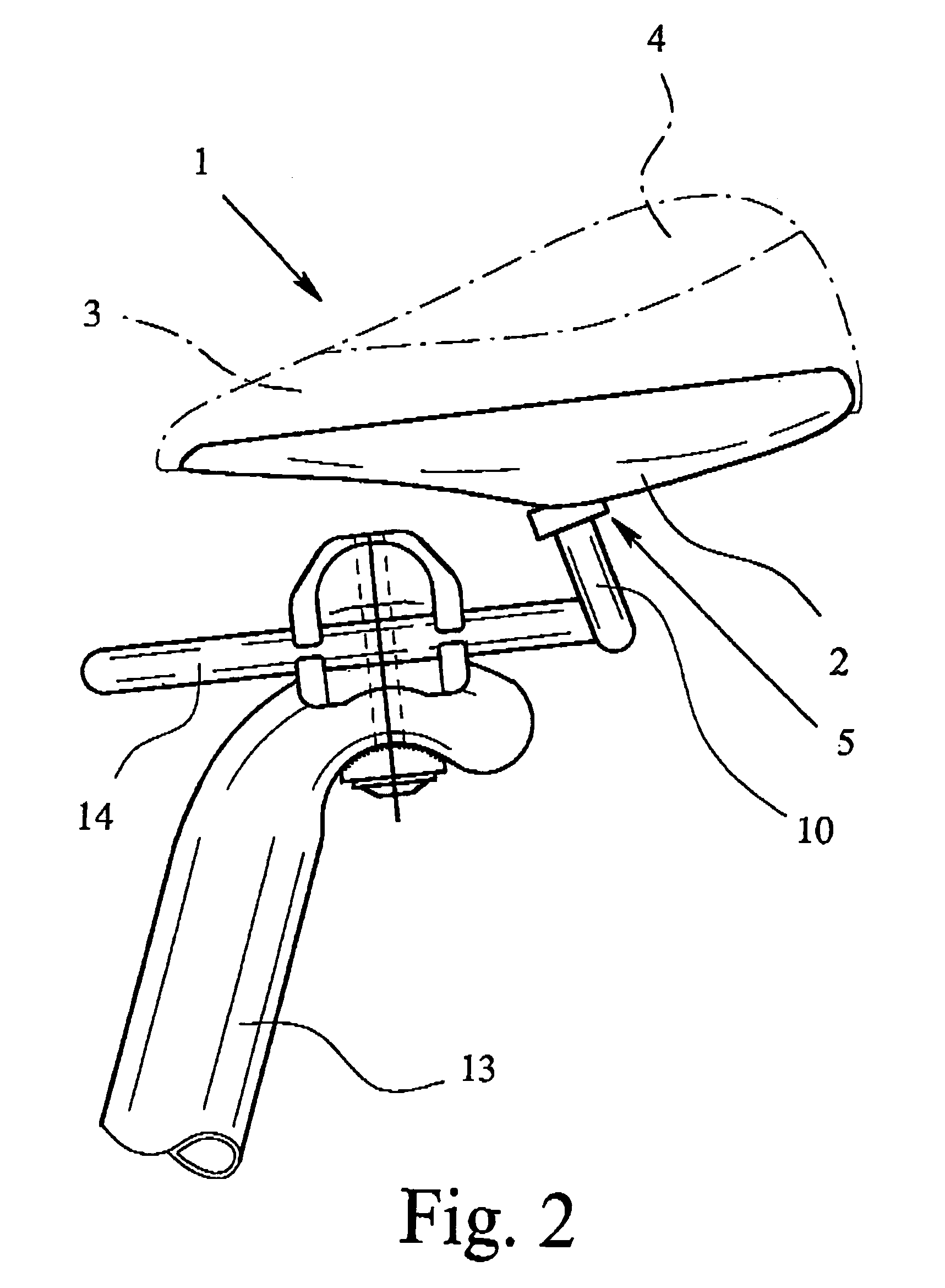
[0031]FIG. 1 shows a bicycle saddle according to a preferred embodiment of the invention, the saddle having two seat halves 1 which are spaced apart from one another and each of which is designed for one half of the buttocks. As is apparent especially from FIG. 2, the seat halves 1 each have a bottom plate 2 and padding 3. For reasons of comfort, the padding 3 is provided with a gel insert 4. The gel insert 4 is used essentially for relief of the sharp-edged ischia. They determine essentially also the distance of the two seat halves 1 from one another or the location of the padding 3. The distance of the ischia for an adult is typically a maximum 90 mm, the distance forward being reduced to roughly 40 mm so that the distance, width and length of the seat halves are dimensioned accordingly. The padding 3 and the gel insert 4 are finally covered with a cover of, for example, leather or an artificial leather material which is not further shown. Otherwise, it can also be provided that t...


PUM


Abstract

A saddle for pedal-powered devices, especially bicycles, with two spaced apart seat halves (1), each of which supports one half of the buttocks, and with a cup joint arrangement on its bottom. The cup joint arrangement (5) has an essentially hollow spherical socket (6) and a cup element (7) which can be moved in it. A support rod (11) has two supports (10), each of which is attached to a respective cup element (7), for connecting the saddle to a saddle support (13) by the support rod (11). The cup joint arrangements (5) each have a device for limiting the range of motion of the cup element (7) in the socket (6). The cup joint axes, around which the cup elements (7) can be moved in their respective socket (6), are each outwardly inclined. Thus, a solid seat on the saddle and ergonomic pedaling are enabled.

Description

BACKGROUND OF THE INVENTION[0001]1. Field of the Invention[0002]The invention relates to a saddle for pedal-powered devices, especially bicycles, with two seat halves which are spaced apart from one another and which are each designed for one half of the buttocks, each seat half having a cup joint arrangement on its bottom, the cup joint arrangement comprising an essentially hollow spherical socket and a cup element which can be moved in it, there being a support rod with two supports which are each attached to the cup element so that the saddle can be connected to a saddle support by means of the support rod and the cup joints each having a means by which the range of motion of the cup element in the socket is limited.[0003]2. Description of Related Art[0004]A saddle of the above mentioned type is known, for example, from German Utility Model DE 201 00 412 U1.[0005]Saddles, especially bicycle saddles, are generally built according to a static principle, in spite of padding, spring ...

Claims


Application Information

Patent Timeline
IPC IPC(8): B62J1/00
CPCB62J1/005
Inventor SCHOLZ, HANS
Owner SCHOLZ HANS
Learn More