
Cable terminating apparatus

a technology for terminating apparatuses and cables, applied in the direction of unstripped conductor connection apparatuses, wire tools, manufacturing tools, etc., can solve the problems of difficult operation, operator discomfort, and cable termination of insulation displacement connection (idc)

Active Publication Date: 2006-09-12
COMMSCOPE TECH LLC
View PDF16 Cites 31 Cited by
  • Summary
  • Abstract
  • Description
  • Claims
  • Application Information

AI Technical Summary

Benefits of technology

The present invention provides a way to position and connect wires in a cable with a connector. The invention includes a support means with positioning means for the wires and a guide means for the connector. The method involves removing insulation from the cable, positioning the wires with the support means, aligning the connector with the support means, and then urging the connector into engagement with the wires. The invention simplifies the process of connecting wires in a cable to a connector.

Problems solved by technology

Insulation displacement connection (IDC) cable termination, where the cable contains a plurality of wires, with a connector containing a plurality of terminals, can be difficult to perform, particularly if the cable contains a number of small diameter wires such as the type typically used for telecommunications applications.
One wire at a time termination is a time consuming operation, and multiple wire termination may cause operator discomfort, because of the stress imposed by impact on those wires.
Moreover, since connectors often break, a field replacement operation is often necessary, complicating the termination efforts.
Using prior art tools to perform the cutting may leave less than a flush cut, leaving wire ends exposed which may touch a shielding or electrically conductive member.

Method used


Image

  • Cable terminating apparatus
  • Cable terminating apparatus
  • Cable terminating apparatus

Examples


Embodiment Construction

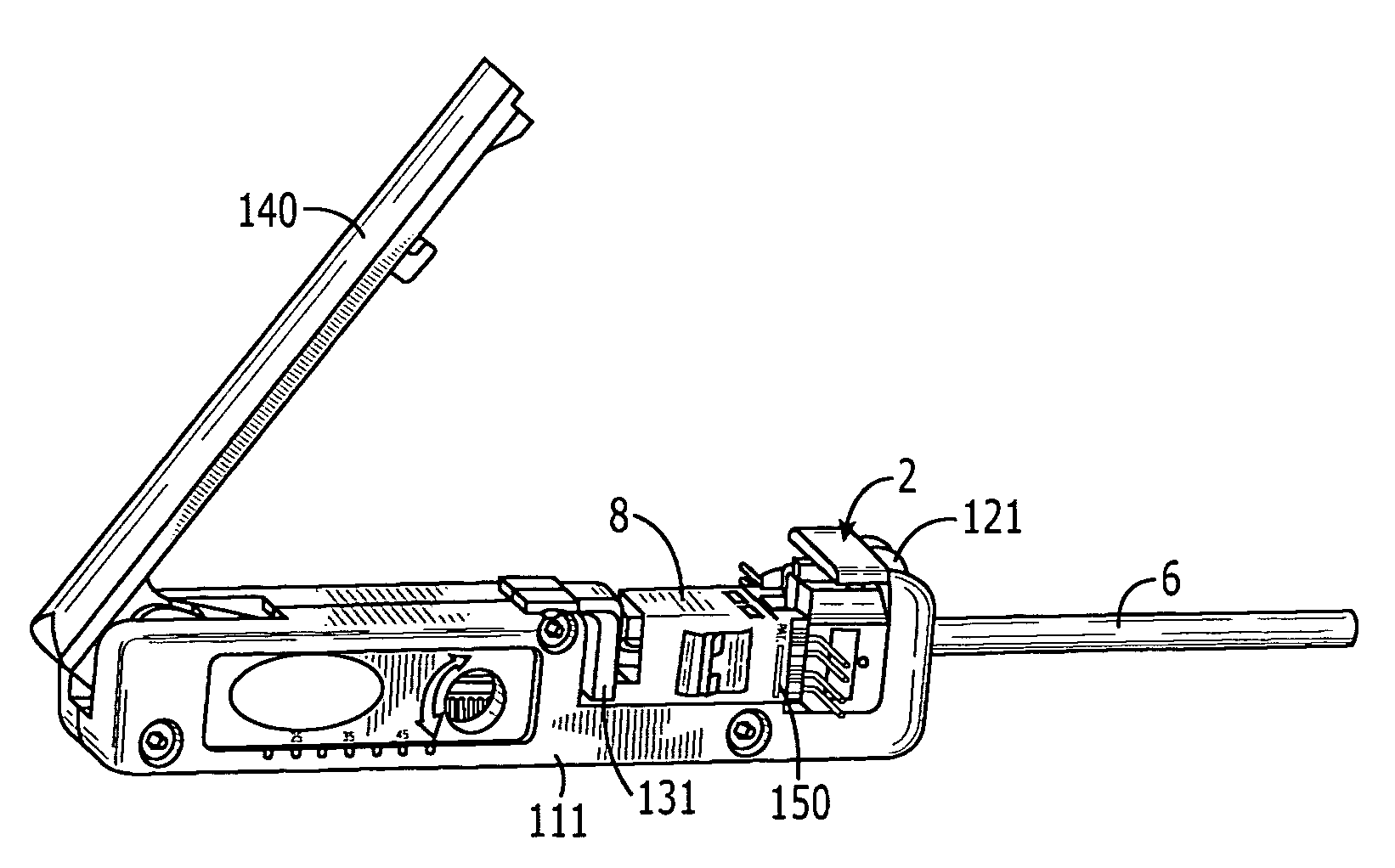
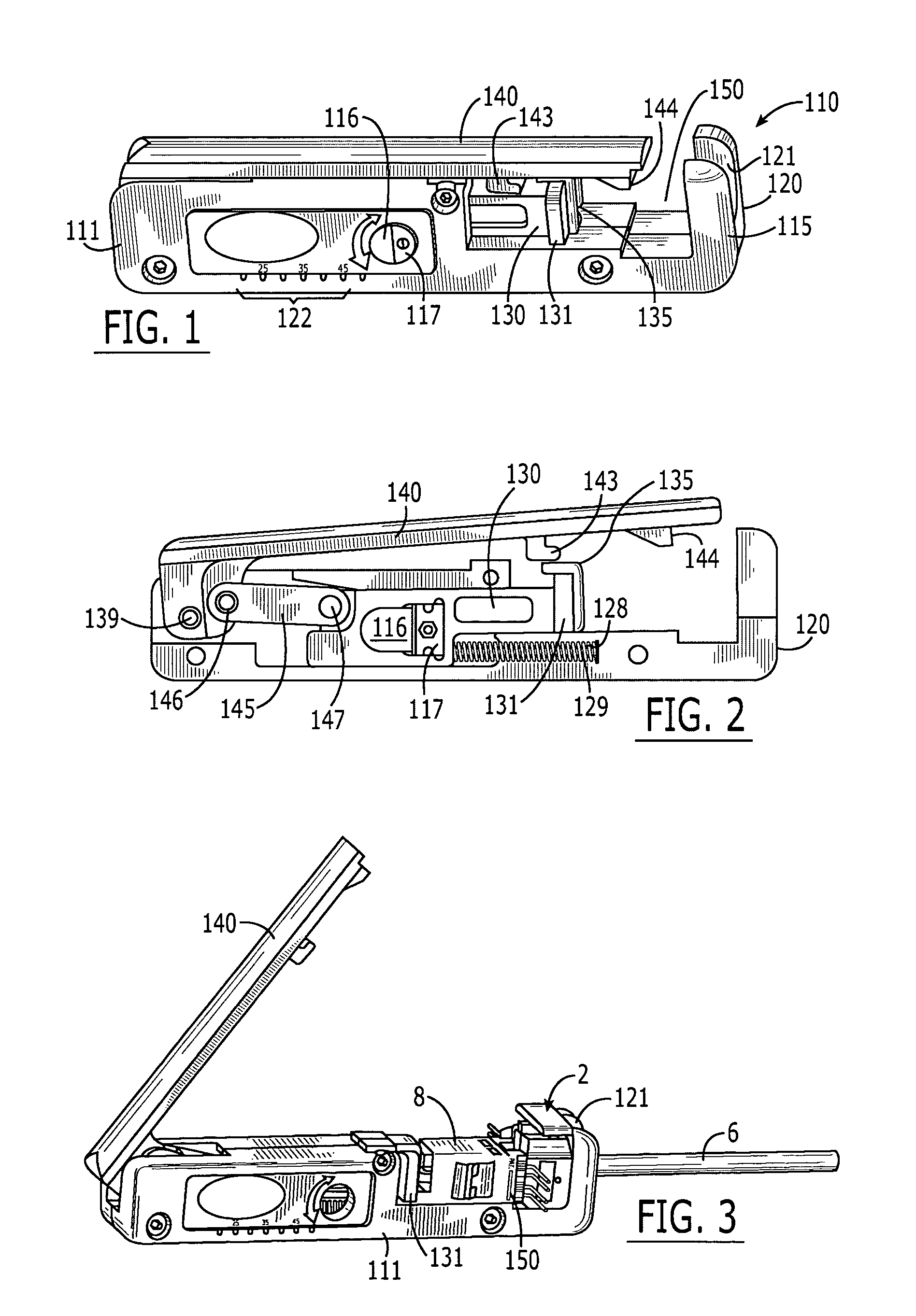
[0024]FIG. 1 shows a preferred embodiment of the invention. A squeezing tool embodiment is shown generally at 110. Also shown is a body 111, comprised of housings 115 and 120. A stripping recess 116 is shown integral to body 111. Contained therein is stripping blade 117, as will be further described below. Measurement scale 122 is also shown, and may be used, inter alia, to determine cable stripping length. Actuation member 130 is seen as well, having associated finger pull 131 and pusher 135.

[0025]Handle 140 is shown in closed position. Handle 140 may also be placed in a locking position, if desired, wherein lug 143 of handle 140 engages in mating relationship with actuation member 130. Lug 144 provides a seating engagement for a cable manager, as is further described below. Cable slot 121 provides a pass through for a cable, as well as mating engagement for a cable boss on a cable manager, as will be further described below.

[0026]FIG. 2 shows the embodiment of FIG. 1 with housing ...


PUM

PropertyMeasurementUnit
squeezing forceaaaaaaaaaa
electrically contactingaaaaaaaaaa
diameteraaaaaaaaaa

Abstract

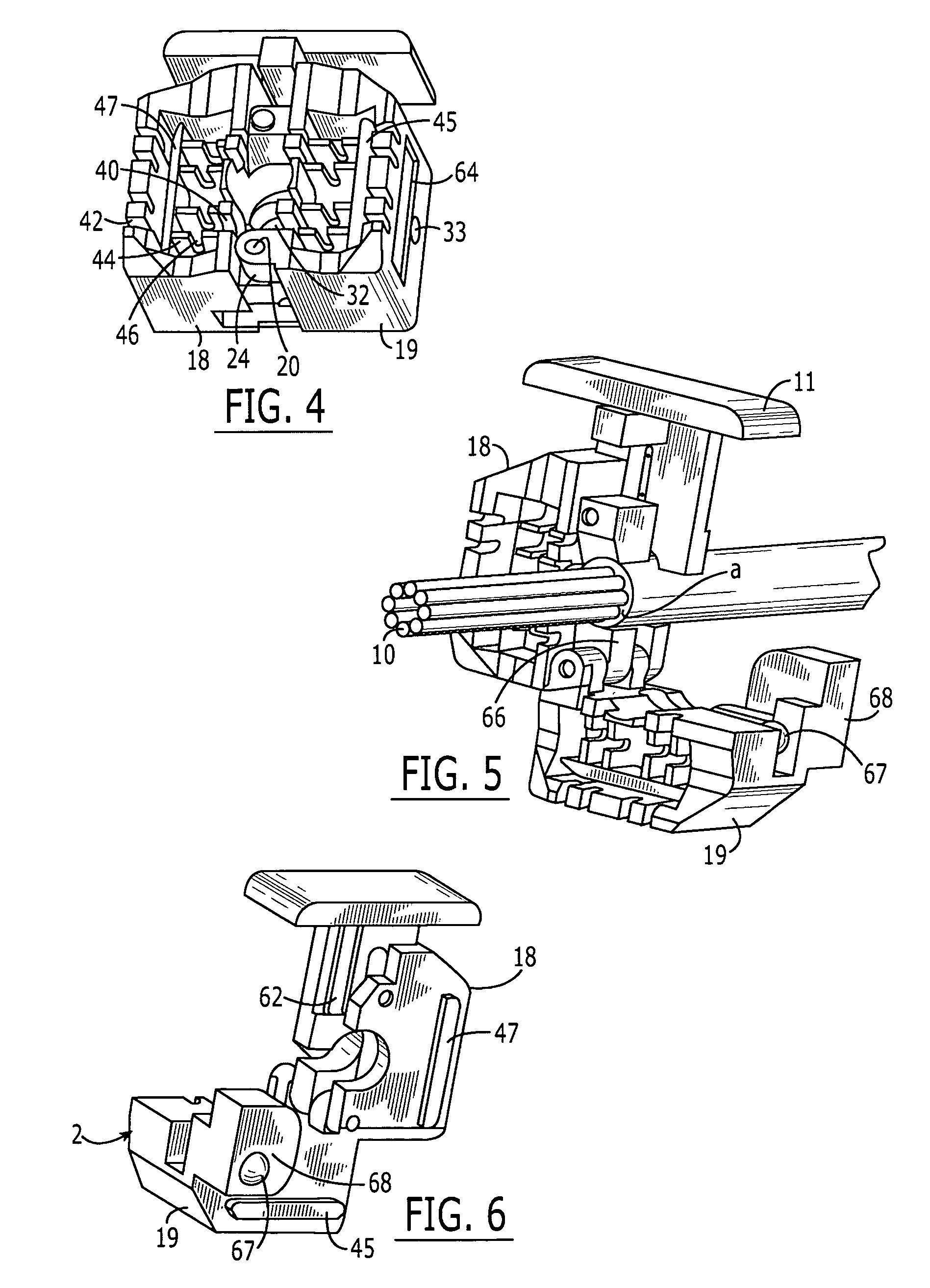
Apparatus and methods are shown for holding a plurality of wires of a cable in fixed positions relative to each other for assisting in the termination of the cable with a connector having plurality of contacts possibly of the insulation displacement type.

Description

FIELD OF THE INVENTION[0001]The present invention relates to apparatus for terminating an electrical cable with a connector and methods of performing such a termination.BACKGROUND OF THE INVENTION[0002]Insulation displacement connection (IDC) cable termination, where the cable contains a plurality of wires, with a connector containing a plurality of terminals, can be difficult to perform, particularly if the cable contains a number of small diameter wires such as the type typically used for telecommunications applications.[0003]Tools for such termination in the prior art typically are impact tools that require inserting wires one at a time into connector terminals, or terminate a number of wires at once. One wire at a time termination is a time consuming operation, and multiple wire termination may cause operator discomfort, because of the stress imposed by impact on those wires. Moreover, since connectors often break, a field replacement operation is often necessary, complicating t...

Claims


Application Information

Patent Timeline
Patent Type & Authority Patents(United States)
IPC IPC(8): B23P19/00B25B25/00H01R43/00H01R43/01
CPCH01R43/015Y10T29/53283Y10T29/5313Y10T29/53209Y10T29/53257Y10T29/53217Y10T29/53222Y10T29/514Y10T29/53243Y10T29/5151Y10T29/53213
Inventor KARRASCH, CHRISTOPHER J.
Owner COMMSCOPE TECH LLC
Learn More