
Inspection unit

a technology of inspection unit and inspection unit, which is applied in the direction of measurement device, semiconductor/solid-state device testing/measurement, instruments, etc., can solve the problems of inability to prepare inspection unit, inability to perform accurate inspection, and fluctuation of impedance or other measurement factors, etc., to achieve the effect of convenient manufacturing and short supply tim

Active Publication Date: 2006-09-05
YOKOWO CO LTD
View PDF1 Cites 21 Cited by
  • Summary
  • Abstract
  • Description
  • Claims
  • Application Information

AI Technical Summary

Benefits of technology

The invention provides an inspection unit that can be easily manufactured and supplied quickly, allowing for immediate inspection of new devices. The inspection unit includes a conductive member with through holes, a first contact probe for non-RF signals, and a second contact probe for RF signals. The first and second contact probes are retained in the conductive member while only the plungers are projected from the through holes. The retainer has second through holes with a common shape and a retainer can be made of insulative material or conductive material with insulative spacers. The second tubular body is longer than the first tubular body. The technical effects of the invention include easy manufacturing, reliable inspection with no need for special probes for every arrangement of pins, and compatibility with small and many types of devices.

Problems solved by technology

On occasion of inspecting electrical performance of the RF device such as a semi-conductor wafer, an IC, or a module, insufficient contacts between the terminals may particularly cause fluctuation of impedance or other measurement factors, which may sometimes vary to change measured values.
Meanwhile, such inspection unit is unable to be prepared prior to developing stage, because in the developing stage of the module and IC of this type, various adjustments are continued along with the inspection, and accordingly, there may be changes in the arrangement of the electrode terminals, such as addition of a grounding terminal.
Nevertheless, even in the developing stage, it is impossible to perform accurate inspection unless a reliable inspection unit is employed.
Under the circumstances, there is a problem that in a case where various inspection units are prepared in the developing stage, it would lead to an enormous increase of cost.
Furthermore, in a case where provisional inspecting tools are used in order to conduct the inspection in the developing stage, and a producer of inspection units starts to produce a definitive version of the inspection unit after completion of the development based on the fixed arrangement of the electrode terminals in the device to be inspected, these may be a problem that it would not be in time for conducting the inspection immediately.
Especially in a case where the producer of the inspection unit is different from the developer of the device, the developer of the device generally have a tendency not to disclose the arrangement of the electrode terminals to the producer of the inspection unit to the final stage of the development, in some cases, which is a serious time factor in preparing the inspection unit.

Method used


Image

  • Inspection unit
  • Inspection unit
  • Inspection unit

Examples


Embodiment Construction

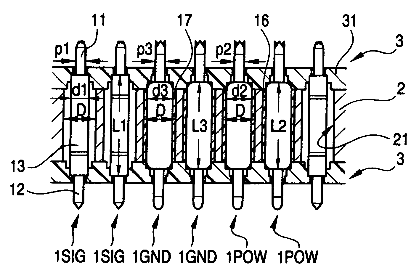
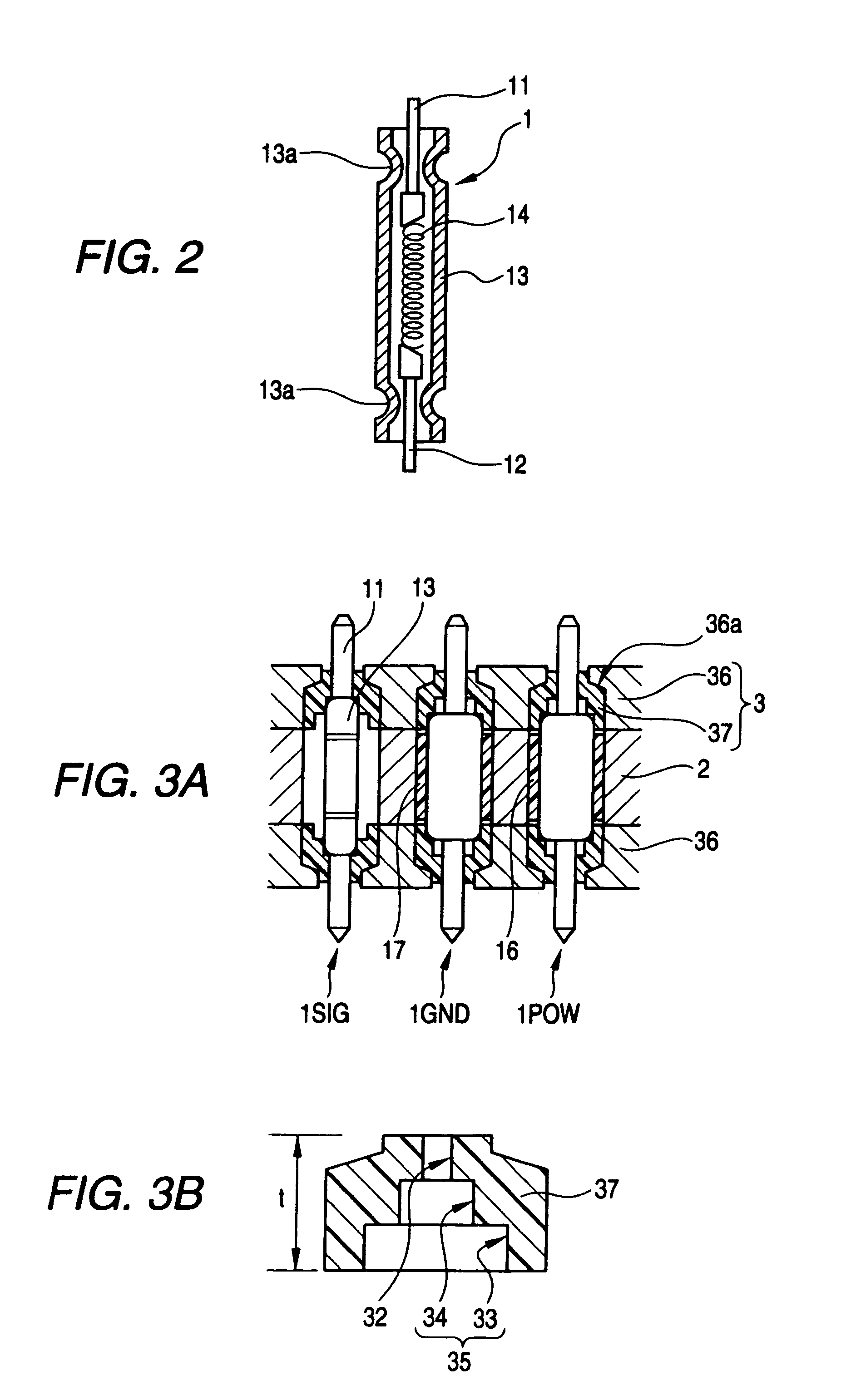
[0031]As shown in FIG. 1, an IC socket according to a first embodiment of the invention comprises a metal block 2 formed with through holes 21. In the through holes 21, there are respectively provided: a contact probe 1SIG for RF signals which serves as a core conductor of a coaxial structure and has a relatively small outer diameter; a contact probe 1POW for power supply which has a larger outer diameter than the contact probe 1SIG; and a contact probe 1GND for grounding which has a larger outer diameter than the contact probe 1SIG.

[0032]Further, a retainer 3 for retaining the contact probes 1SIG, 1POW, 1GND is provided on at least one face of the metal block 2 in such a manner that these probes do not escape from the metal block 2, while only plungers 11 of the contact probes 1SIG, 1POW, 1GND are projected the in this embodiment, a structure including the through holes 21 and the retainer 3 is common with respect to all the contact probes 1SIG, 1POW, 1GND.

[0033]Specifically, all t...


PUM


Abstract

A conductive member has a first face adapted to be mounted on a board on which an inspection circuit is arranged and a second face adapted to be opposed to a device to be inspected. The conductive member is formed with a plurality of first through holes having a first common diameter and communicating the first face with the second face. A first contact probe is provided with a first tubular body having a second diameter which is smaller than the first diameter, and a first plunger retractably projected from one end of the first tubular body. A second contact probe is provided with a second tubular body having a third diameter which is smaller than the second diameter, and a second plunger retractably projected from one end of the second tubular body. A retainer is formed with a plurality of second through holes having a common shape, and provided on at least the second face of the conductive member so as to communicate the first through holes with the second through holes, so that the first contact probe and the second contact probe are retained in the conductive member while only the first plunger and the second plunger are projected from one ends of the second through holes.

Description

BACKGROUND OF THE INVENTION[0001]The present invention relates to an inspection unit for a high frequency / high-speed device for ensuring reliable connection between the inspection unit and the device to be inspected, on occasion of inspecting its electrical performance, before a module of a high frequency / high-speed circuit such as an amplifier circuit, a mixer circuit, a filter circuit, a memory, a CPU, etc. or an IC to be incorporated in a mobile phone, for example, has been assembled to a circuit board. In this specification, the term “high frequency” refers to an analogue signal having a high frequency (1 GHz or more), while the term “high-speed” refers to a digital signal having very short pulse width and pulse interval, and both of which are hereinafter collectively referred to as RF (radio frequency).[0002]On occasion of inspecting electrical performance of the RF device such as a semi-conductor wafer, an IC, or a module, insufficient contacts between the terminals may partic...

Claims


Application Information

Patent Timeline
Patent Type & Authority Patents(United States)
IPC IPC(8): G01R31/02
CPCG01R1/06772G01R1/07371G01R1/07314G01R31/26H01L22/00G01R1/067
Inventor YOSHIDA, TAKUTO
Owner YOKOWO CO LTD
Learn More