Liquid chromatography column having metal to metal seals

a liquid chromatography and metal seal technology, applied in the direction of ion-exchangers, separation processes, instruments, etc., can solve the problem of reducing the resolving capability of the hplc apparatus

Active Publication Date: 2006-09-05
AGILENT TECH INC
View PDF11 Cites 38 Cited by
  • Summary
  • Abstract
  • Description
  • Claims
  • Application Information

AI Technical Summary

Problems solved by technology

Broad peaks, caused by poor column performance, are undesirable as they may allow minor components of the mixture to be masked by major components

Method used


Image

  • Liquid chromatography column having metal to metal seals
  • Liquid chromatography column having metal to metal seals
  • Liquid chromatography column having metal to metal seals

Examples


Embodiment Construction

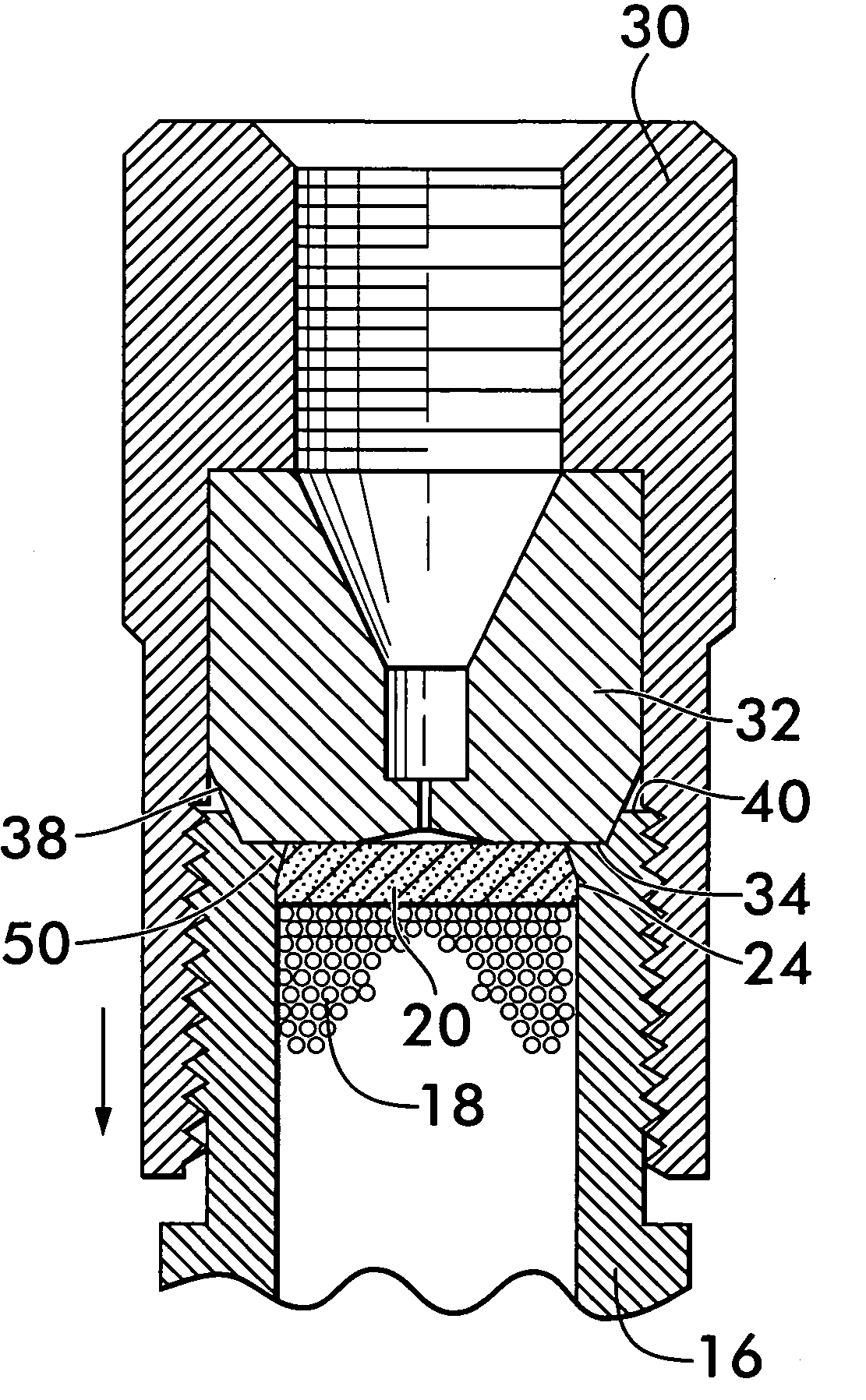
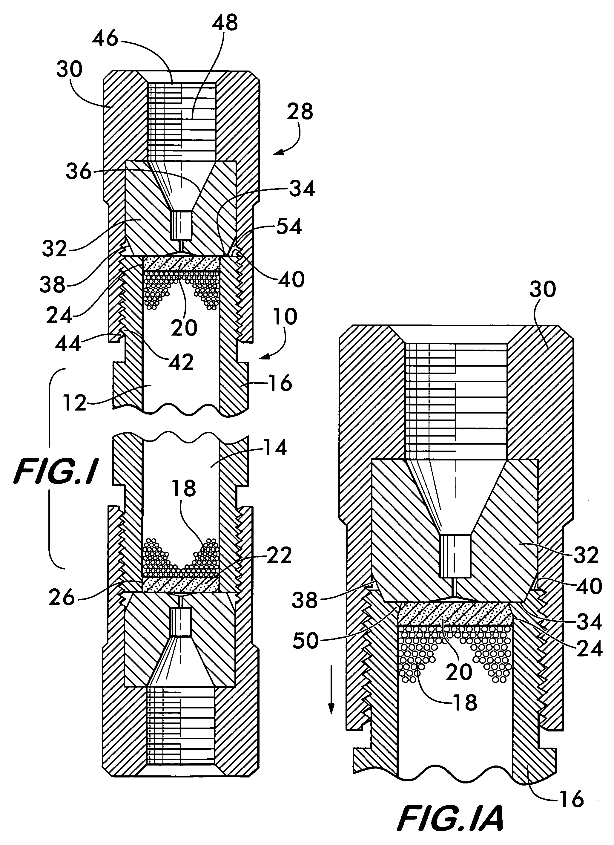
[0014]FIG. 1 shows a liquid chromatography column 10 according to the invention. Column 10 may be any type of column used in liquid chromatography, examples of which include an analytical column, a preparatory column and a guard column. The columns may have outer diameters that range between about 0.25 inches and about 1.125 inches and lengths up to about 10 inches.

[0015]Column 10 comprises a chamber 12, preferably defined by the bore 14 of a tube 16. Bore 14 contains a packing medium 18 used in liquid chromatography analysis, for example, silane derivatized silica spheres having a diameter of less than 20 microns. The packing medium is packed under high pressure and is retained within bore 14 by porous metal plugs 20 and 22 that are inserted into the bore at openings 24 and 26 in opposite ends of tube 16. The plugs are inserted and compress the packing material to reestablish some of the pressure lost after the packing process when the pressure is removed to complete assembly of th...


PUM


Abstract

A column for liquid chromatography includes a chamber adapted to receive packing medium. Openings in the chamber allow fluid to pass through it. Porous plugs in the chamber retain the packing medium. A fitting has a contact surface that engages a landing area on the chamber surrounding one of the openings. Engagement of the contact surface with the landing area forms a metal to metal seal between the fitting and the chamber. A method of sealing a column for liquid chromatography is also disclosed. The method involves a chamber containing packing medium, the chamber having an opening surrounded by a landing area. The method includes providing a compression fitting having a contact surface and compressing the contact surface against the landing area to form a fluid tight seal between the compression fitting and the chamber.

Description

BACKGROUND OF THE INVENTION[0001]High performance liquid chromatography (HPLC) is a process by which one or more compounds from a chemical mixture may be separated and identified. A transport liquid, for example a solvent, is pumped under high pressure through a column of packing medium, and a sample of the chemical mixture to be analyzed is injected into the column. As the sample passes through the column with the liquid, the different compounds, each one having a different affinity for the packing medium, move through the column at different speeds. Those compounds having greater affinity for the packing material move more slowly through the column than those having less affinity, and this speed differential results in the compounds being separated from one another as they pass through the column.[0002]The transport liquid with the separated compounds exits the column and passes through a detector, which identifies the molecules, for example by spectrophotometric absorbance measur...

Claims


Application Information

Patent Timeline
IPC IPC(8): B01D15/08
CPCB01D15/20B01D15/22G01N30/6026G01N2030/522G01N30/6021G01N30/603G01N30/6069
Inventor WILLIS, FRANK M.MACHAMER, CLYDE L.
Owner AGILENT TECH INC
Why Eureka
Try Eureka