
Sander with variable position handle

a technology of a handle and a sander, which is applied in the field of woodworking, can solve the problems of large time and effort required in the implementation of polishers/sanders, the difficulty of achieving the effect of a single position, and the difficulty of achieving a single position

Inactive Publication Date: 2006-09-05
BLACK & DECKER INC
View PDF6 Cites 31 Cited by
  • Summary
  • Abstract
  • Description
  • Claims
  • Application Information

AI Technical Summary

Problems solved by technology

Finishing operations such as sanding and polishing often require significant time and effort to remove imperfections from the workpiece.
As a result, a user may typically implement polishers / sanders for a significant amount of time.
In addition, since most finishing operations are conducted near the end of a project (e.g., after assembly) a user has often expended large amounts of time, effort, expense in creating a craftsman-like project prior to finishing.
As such, a user may become fatigued due to the particular orientation, due to vibrations, and the like.
User fatigue may decrease overall satisfaction with the tool, reduce working intervals, and the like.

Method used


Image

  • Sander with variable position handle
  • Sander with variable position handle
  • Sander with variable position handle

Examples


Embodiment Construction

[0016]Reference will now be made in detail to the presently preferred embodiments of the invention, examples of which are illustrated in the accompanying drawings. Those of skill in the art will appreciate that a variable position handle in accordance with the present invention may be implemented with a variety of power finishing tools. Suitable power finishing tools include random orbit sanders, polishers (random orbit and orbital), orbital sanders, quarter pad sanders, half pad sanders, belt sanders, grinders, hand planers, hand jointer, and the like.

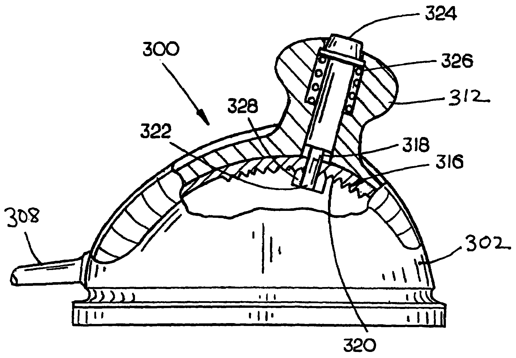
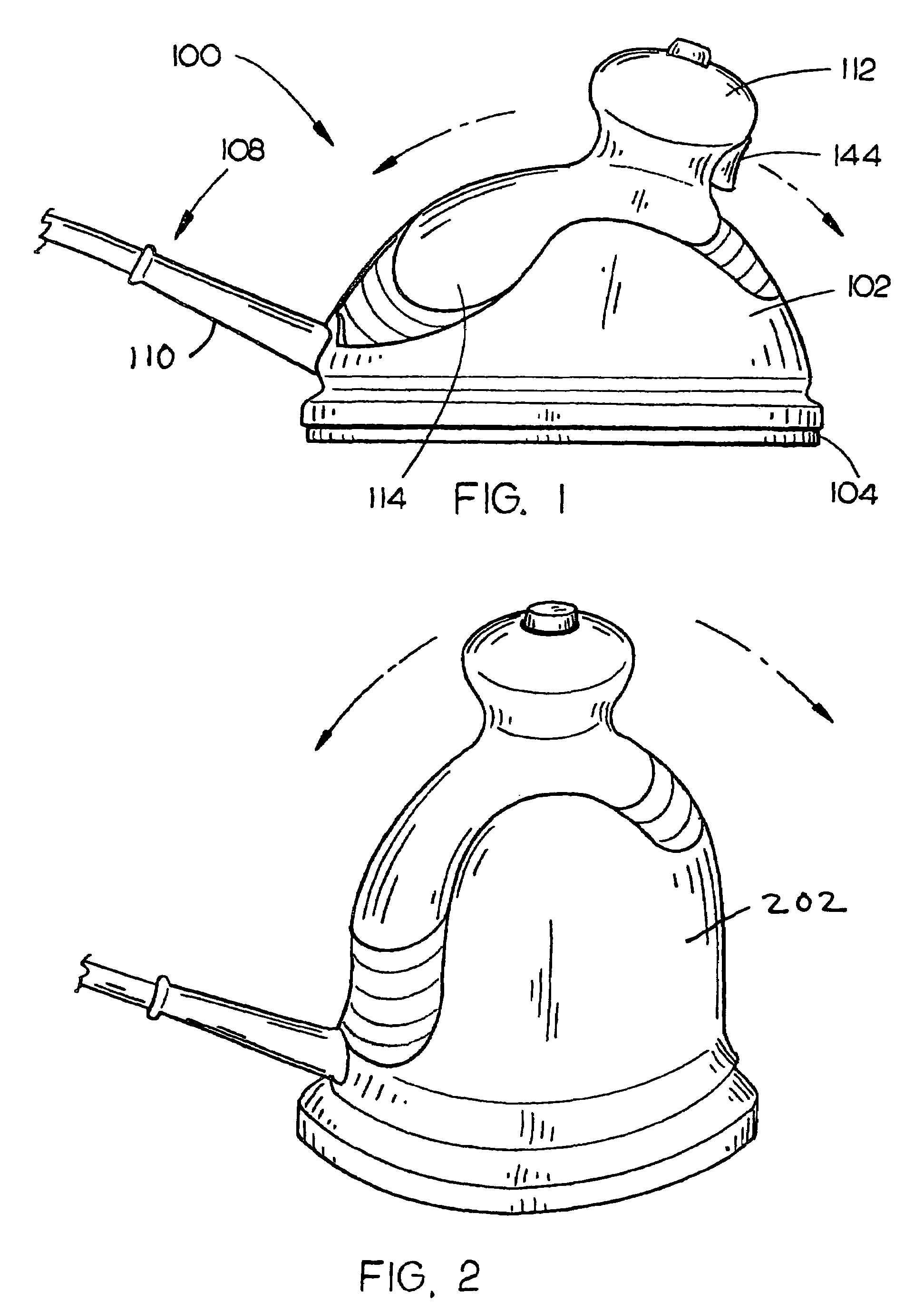
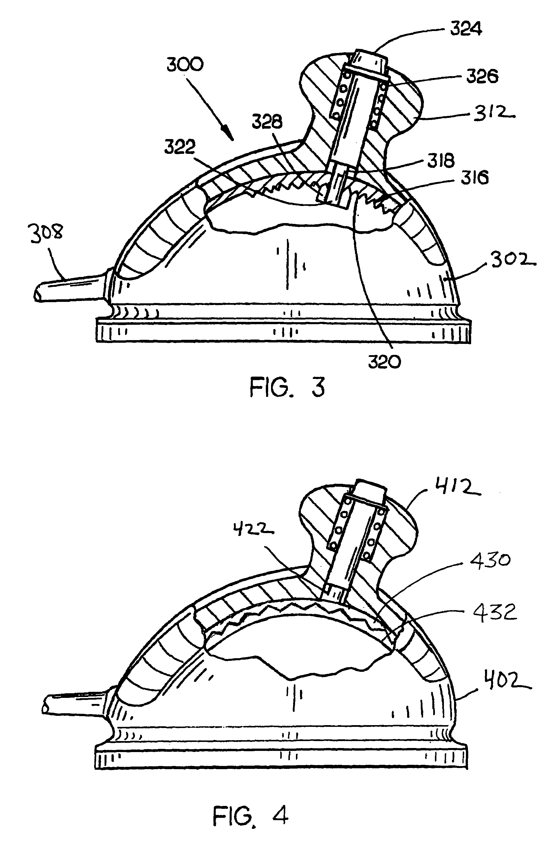
[0017]Referring to FIG. 1, a power finishing tool, such as random orbit sander 100, in accordance with an embodiment of the present invention is disclosed. A motor housing 102 for containing a motor for driving a working element is included in the sander 100. For example, the random orbit sander 100 may include a hemispherical motor housing 102 configured to contain various sander components such as a motor for rotating / orbiting an op...


PUM


Abstract

The present invention is directed to a power finishing tool having a variable position handle. In aspects of the present invention, a power finishing tool includes a motor housing for containing a motor configured to drive a working element. A variable position handle such as linear handle is adjustable generally toward / away from a power cord such that the power cord is maintained in a standard orientation (i.e., toward the rear of the tool / the direction toward a user). In a further aspect a joystick type variable handle is configured to pivot about a Z-axis extending through the power finishing tool. Suitable adjustment mechanisms include a track type mechanism wherein the handle travels along a track, a rotating bracket mechanism for permitting linear adjustment of the handle may be included for varying the position of the handle, and a ball and socket mechanism. An electrical switch for controlling operation of the power finishing tool may be mounted on the handle for controlling the motor included in the power finishing tool or alternatively to the housing in a location so as not to interfere with a user's grasp but permit efficient access. A securing mechanism such as a biased securing mechanism is configured to fix the position of the handle with respect to the motor housing is further included to secure the handle such as a pommel in a desired orientation. Suitable securing mechanisms include friction locks, positive stop (incremental locking mechanisms), or the like for securing the handle with respect to the motor housing.

Description

CROSS REFERENCE[0001]The present application claims priority under 35 U.S.C. §119(e) to U.S. Provisional Patent Ser. No. 60 / 516,144, entitled: Sander Having Variable Position Handle, filed on Oct. 31, 2003, which is hereby incorporated by reference in its entirety.FIELD OF THE INVENTION[0002]The present invention relates to the field of woodworking and particularly to a finishing apparatus having a variable position handle.BACKGROUND OF THE INVENTION[0003]Finishing operations such as sanding and polishing often require significant time and effort to remove imperfections from the workpiece. For example, woodworkers typically implement a random orbit sander to remove surface imperfections prior to applying coatings, stains, and the like. In this instance, a user may make repeated passes with sanding pads / paper (working element) having sequentially smaller grit size in order remove large imperfections quickly, while correcting smaller defects with finer grit sandpaper during subsequent...

Claims


Application Information

Patent Timeline
IPC IPC(8): B24B23/00
CPCB24B23/005B24B23/02B25F5/02Y10T16/44Y10T16/476
Inventor ETTER, MARK A.BOYD, P. BRENT
Owner BLACK & DECKER INC
Learn More