
Pinout views for allowed connections in GUI

a gui and pinout technology, applied in the field of configuration and programming programmable devices, can solve the problems of time-consuming and expensive, tedious and time-consuming initial programming of a highly complex device, and achieve the effect of rapid configuration of enormously complex programmable devices

Inactive Publication Date: 2006-08-29
CYPRESS SEMICON CORP
View PDF13 Cites 12 Cited by
  • Summary
  • Abstract
  • Description
  • Claims
  • Application Information

AI Technical Summary

Benefits of technology

[0011]Disclosed herein is a method for improving and streamlining the configuration of highly complex programmable devices such as programmable single-chip systems to perform the functions required of each programmed device configuration. The method disclosed is user-friendly, enabling a user of normal skills to rapidly configure enormously complex programmable devices with multiple configurations.

Problems solved by technology

The complexity of a programmable device, most particularly a programmable single-chip system, requires complex programming of each of its configurations which can be stored.
Initial programming of a highly complex device, though, can be tedious and time consuming.
However, even with current configuration tools, a programmer must track a very large number of lines of programming and device characteristics in order to properly establish a complex device configuration.
The validity of the connection was only verifiable in complex simulation or in actual device usage, both of which are time-consuming and expensive.
Both of these methods have a problem in that searching for the set of allowed connections for a given pin is laborious and error-prone.
It is very difficult for a user to determine the entire set of allowable connections for a pin if a wire trace needs to be performed, or if each label needs to be manually scanned, for each allowable connection.
Configuration errors are often found only in simulation of the end configuration or in actual device testing.
By the time these stages are reached, the complexity of the configuration task can have an error source buried deep in configuration code.

Method used


Image

  • Pinout views for allowed connections in GUI
  • Pinout views for allowed connections in GUI
  • Pinout views for allowed connections in GUI

Examples


Embodiment Construction

[0022]Reference will now be made in detail to the preferred embodiments of the invention, examples of which are illustrated in the accompanying drawings. While the invention will be described in conjunction with the preferred embodiments, it will be understood that they are not intended to limit the invention to these embodiments. On the contrary, the invention is intended to cover alternatives, modifications and equivalents, which may be included within the spirit and scope of the invention as defined by the appended claims. Furthermore, in the following detailed description of the present invention, numerous specific details are set forth in order to provide a thorough understanding of the present invention. However, it should be understood by one of ordinary skill in the art that the present invention may be practiced without these specific details. In other instances, well-known methods, procedures, components, and circuits have not been described in detail so as not to unnecess...


PUM


Abstract

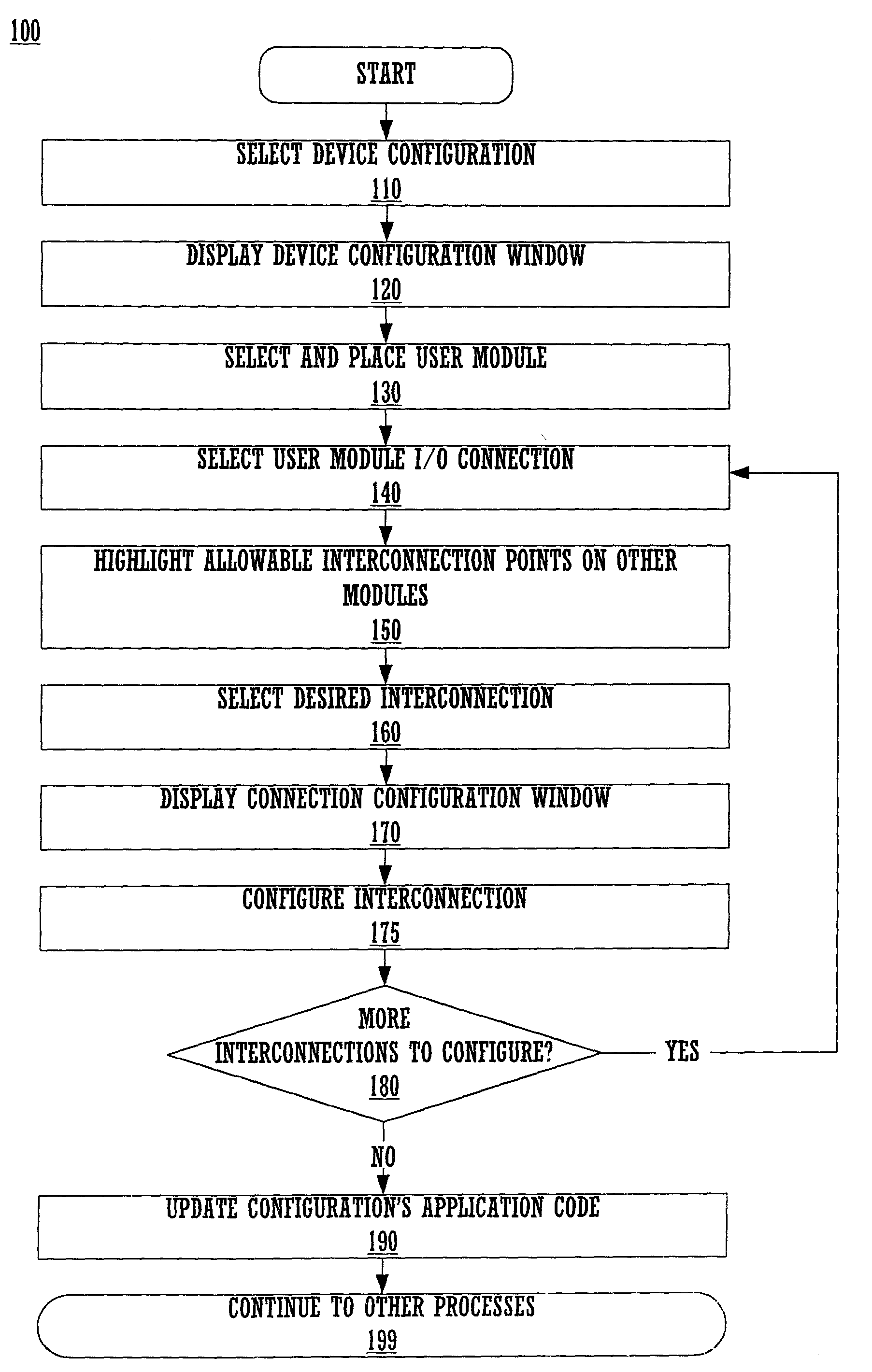
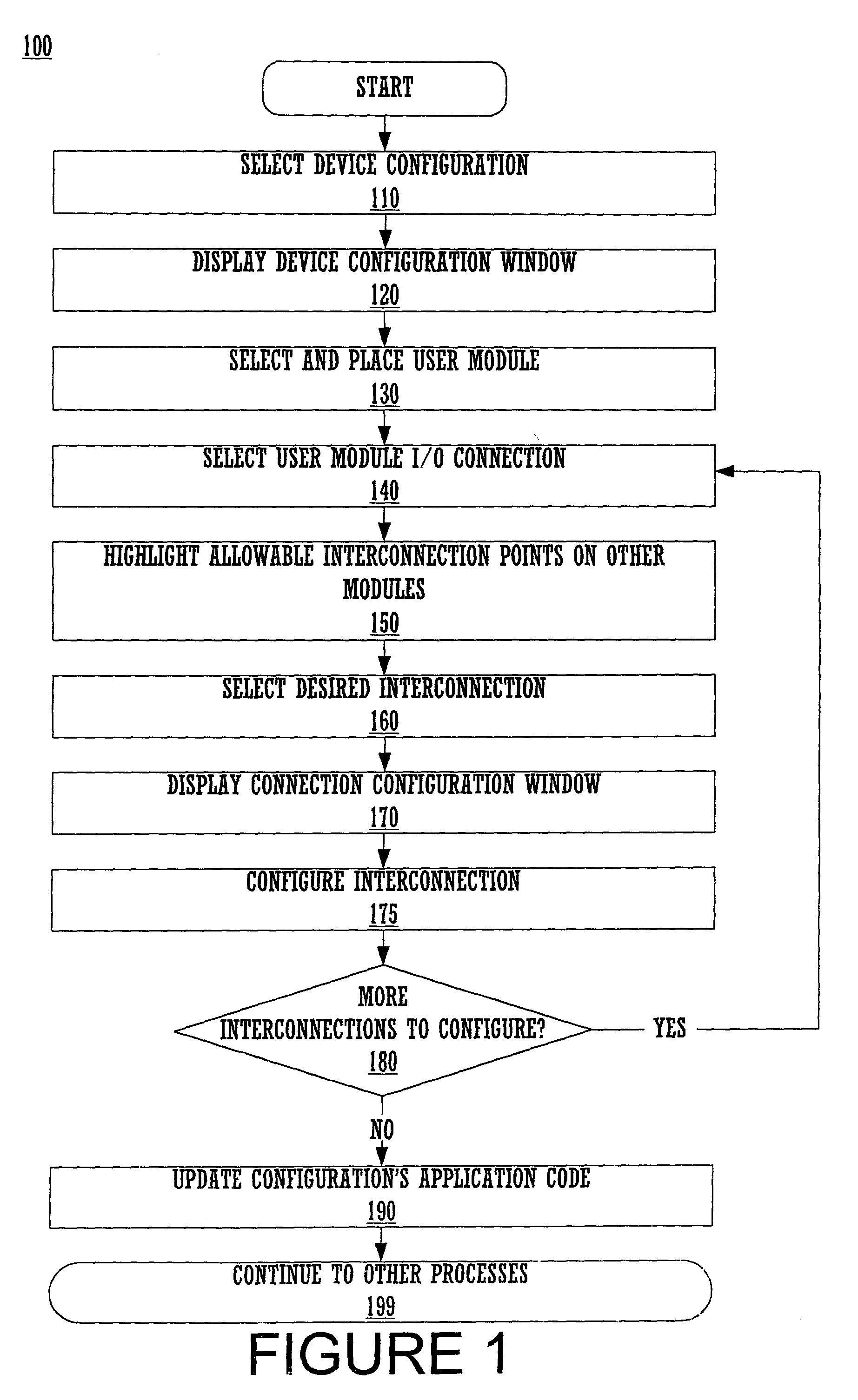
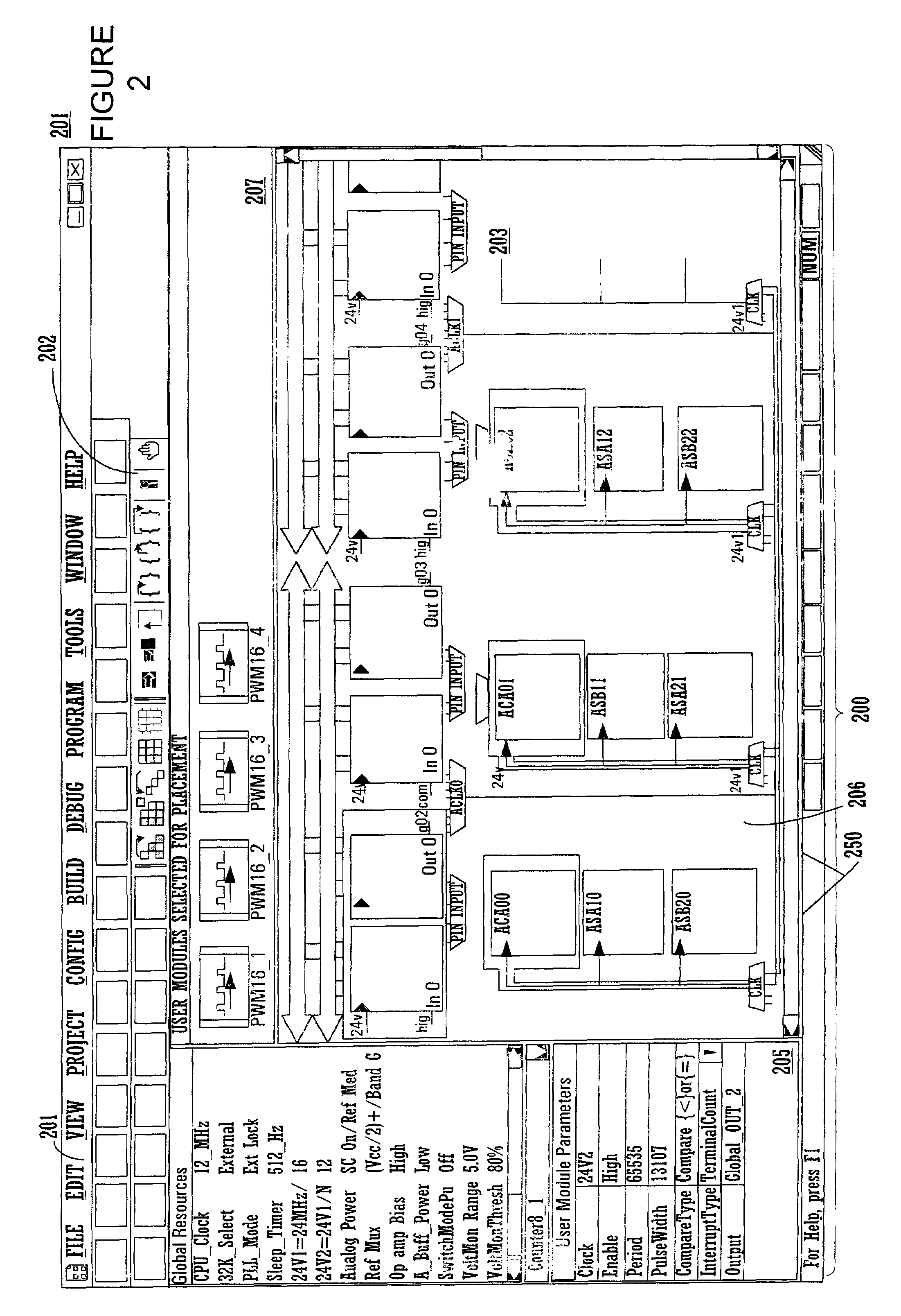
Embodiments of the present invention relate to a method for configuring functional interconnections in a programmable device. The method comprises displaying a graphical user interface, which presents a graphical depiction of the programmable device, selecting a functional user module in the graphical user interface, selecting an interconnect input or output on the user module and displaying a graphical representation of allowable connections for the pin by highlighting those allowable connections in the graphical user interface. The desired interconnection is then selected and selection options for configuring the interconnection can be presented in and selected from a pop-up window or a drop-down list in the graphical user interface.

Description

FIELD OF THE INVENTION[0001]Embodiments of the present invention relate to the field of configuring and programming programmable devices.BACKGROUND OF THE INVENTION[0002]Application-specific integrated circuits (ASICs), have been supplanted more and more by integrated circuits (ICs) that can be programmed to fulfill multiple functions. There are now many various programmable logic architectures, including, for example, programmable logic devices (“PLDs”), programmable logic arrays (“PLAs”), complex programmable logic devices (“CPLDs”), field programmable gate arrays (“FPGAs”) and programmable array logic (“PALs”). Although there are differences between these various architectures, each of the architectures typically include a set of input conductors coupled as inputs to an array of logic whose outputs, in turn, act as inputs to another portion of the logic device. Complex Programmable Logic Devices (“CPLDs”) are large scale PLDs that, like many programmable architectures, are config...

Claims


Application Information

Patent Timeline
Patent Type & Authority Patents(United States)
IPC IPC(8): G06F17/50
CPCG06F17/5054G06F30/34
Inventor ANDERSON, DOUGLAS H.SEGUINE, DENNIS
Owner CYPRESS SEMICON CORP
Learn More