
Sub-symbol parallel interference cancellation

a parallel interference and sub-symbol technology, applied in the field of communication, can solve the problems of significantly outperforming conventional techniques at an affordable computational cost, and achieve the effects of reducing complexity, reducing computational costs, and canceling multiple user interferen

Active Publication Date: 2006-08-29
THE MITRE CORPORATION
View PDF5 Cites 32 Cited by
  • Summary
  • Abstract
  • Description
  • Claims
  • Application Information

AI Technical Summary

Benefits of technology

[0012]One technique uses parallel interference cancellation (PIC) on a chip-by-chip basis. Particularly, a decoupled binary minimum mean squared error (MMSE) estimate is applied for each user at each time sample, instead of waiting for a complete symbol estimate. According to another aspect, the pseudorandom properties of the spreading codes lead to a conditional expectation based on an underlying mixture-of-Gaussians (MG) distribution. This results in performance nearly as high as the single-user bound, even at high loads. Furthermore, these techniques significantly outperform conventional ones at an affordable computational cost.
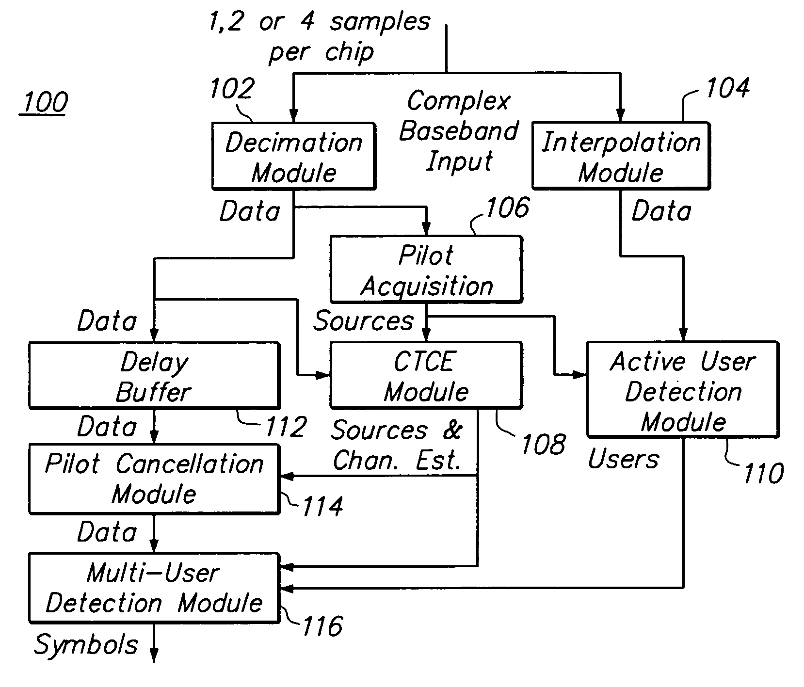
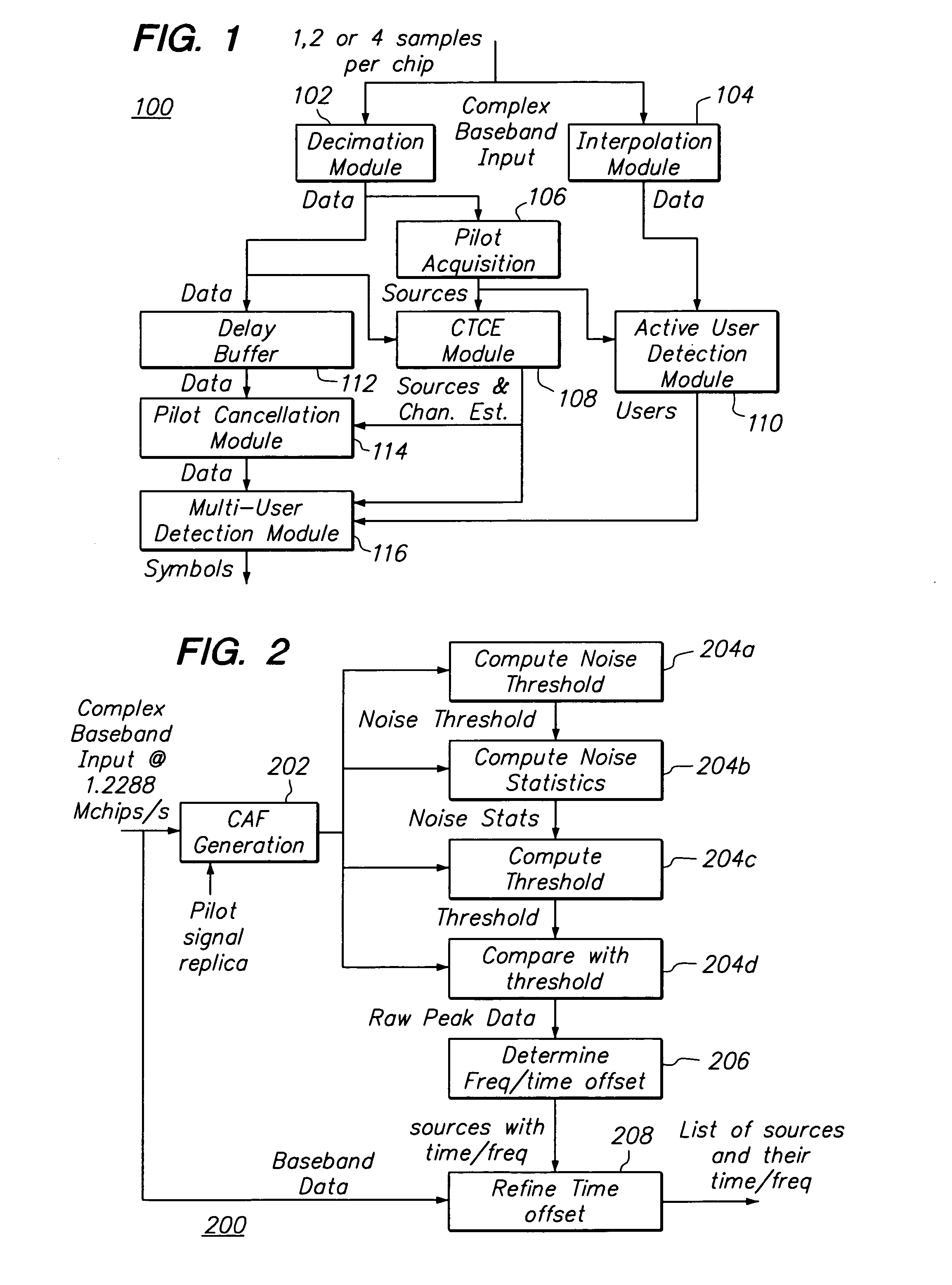
[0013]Another aspect of the present invention cancels multiple user interference in a communications system wherein a plurality of users communicate over a shared channel by receiving a set of data (e.g., baseband data) that provides a plurality of discrete values produced at a sub-symbol interval that is less than a full symbol period, and estimating bits for a symbol corresponding to a given user by interpolating the signature waveforms for at least some of the plurality of users to a common sampling lattice of the received set of data. This aspect can be applied to various MUD approaches including the Mixed Gaussian Demodulator, PIC, partial PIC, and the Decoupled Kalman Demodulator and provides a substantial reduction in complexity since the interpolation of the binary signature waveforms can be performed easily with lookup tables, whereas the interpolation of each source to chip center requires filtering operations involving traditional multiply-accumulate structures.

Problems solved by technology

Furthermore, these techniques significantly outperform conventional ones at an affordable computational cost.

Method used


Image

  • Sub-symbol parallel interference cancellation
  • Sub-symbol parallel interference cancellation
  • Sub-symbol parallel interference cancellation

Examples


Embodiment Construction

[0034]In the following description, for purposes of explanation, numerous details are set forth, including particular equations, in order to provide an understanding of one or more embodiments of the present invention. However, it is and will be apparent to one skilled in the art that certain specific details are not required in order to practice the present invention. For example, the details of one aspect of the invention may not be required to practice another aspect of the present invention. For ease of description, the description is separated into separate sections pertaining to various aspects of the present invention.

[0035]As indicated, each aspect of the present invention can be embodied in various forms, including computer implemented methods, computer program products, communications systems and networks, receivers, transmitters and transceivers, and the like. For example, in one embodiment a hand held device such as a cellular telephone includes conventional memory, as w...


PUM


Abstract

Reduction of multiple access interference, in one example for asynchronous CDMA systems using long codes. In one aspect, parallel interference cancellation (PIC) implements a decoupled estimate, preferably non-linear and applied at chip intervals. According to another aspect, interference is cancelled using a technique that estimates bits for a symbol by interpolating signature waveforms for users to a common sampling lattice of the received data. According to another aspect, multi-stage, hybrid multi-stage, and reconfigurable recursive multi-stage multi-user detection architectures and corresponding processes are provided.

Description

CROSS REFERENCE TO RELATED APPLICATIONS[0001]This application claims the benefit under 35 U.S.C. 119(e) of provisional application 60 / 443,655, filed Jan. 30, 2003, entitled “Multi-User Detection Techniques for CDMA,” the entire contents of which are hereby incorporated by reference.BACKGROUND OF THE INVENTION[0002]1. Field of the Invention:[0003]This invention relates generally to communications, more particularly to improving communication system performance through interference cancellation, and still more particularly to improved cancellation of multiple access interference in a code division multiple access communications environment.[0004]2. Description of the Related Art:[0005]Code Division Multiple Access (“CDMA”) provides an effective communications technique for several users to share a communications channel. Unfortunately, when the channel becomes overcrowded, the conventional CDMA receiver performs poorly and multiple access interference (“MAI”) can severely degrade perf...

Claims


Application Information

Patent Timeline
Patent Type & Authority Patents(United States)
IPC IPC(8): H04B1/69H04B1/707H04B1/713
CPCH04B1/71075H04B1/7103
Inventor DUNYAK, JAMES P.FITE, JOHN D.SHAPIRO, JEROME M.
Owner THE MITRE CORPORATION
Learn More