
Polymer SP insulator

a technology of insulator and polymer, which is applied in the direction of supporting insulators, insulating bodies, electrical appliances, etc., can solve the problems of not easy to settle within the strict tolerance, and not easy to satisfy the strict requirements of overall length tolerance of sp insulators, so as to achieve easy control of overall length tolerance, suppress the increase of parallelism or eccentricity, and ensure the effect of flashover distan

Active Publication Date: 2006-08-22
NGK INSULATORS LTD
View PDF13 Cites 5 Cited by
  • Summary
  • Abstract
  • Description
  • Claims
  • Application Information

AI Technical Summary

Benefits of technology

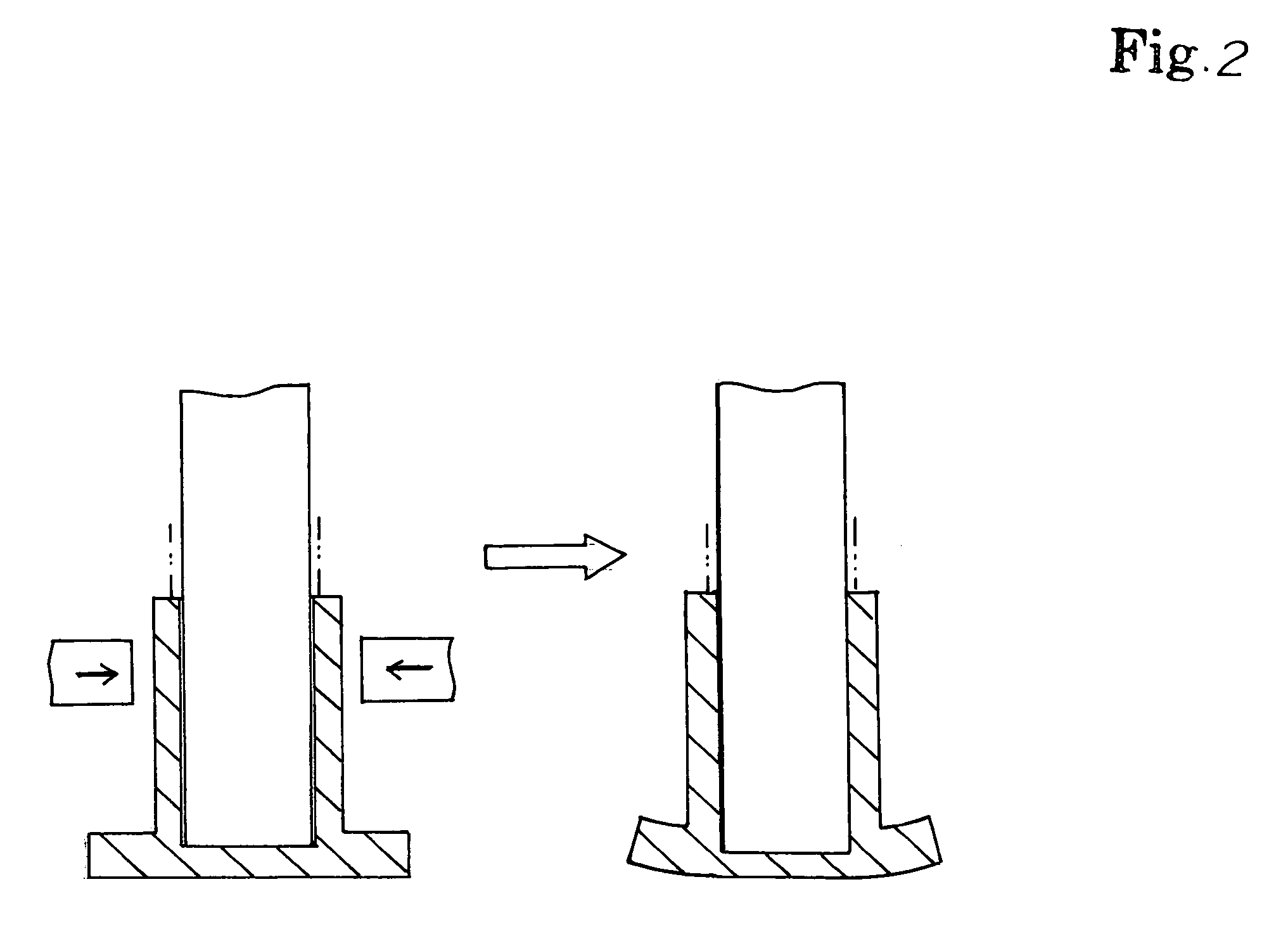
The polymer SP insulator of the invention has a flat plate for adjusting its length, and a stress concentration portion for controlling its overall length and tolerance within the required range. The insulator can easily control the parallelism and eccentricity within the required range of ANSI standard. Additionally, a non-crimping portion can be provided to suppress increase of parallelism or eccentricity due to deformation of the flange. The insulator overall length can be extended economically while ensuring flashover distance and enhancing mechanical strength.

Problems solved by technology

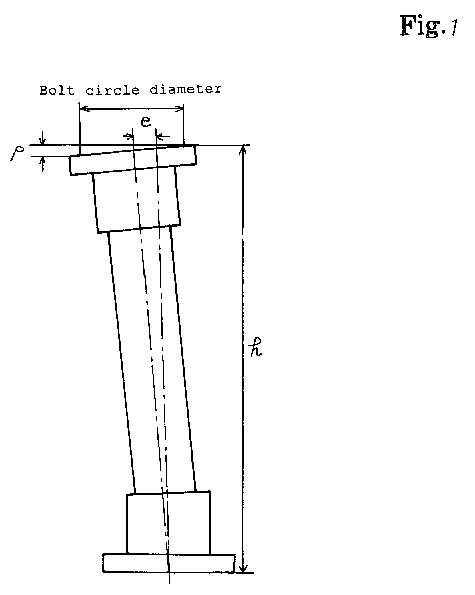
Due to these reasons, it is not easy to satisfy the strict requirements of overall length tolerance of SP insulator, such as overall length tolerance of ANSI standard.
Accordingly, as for the parallelism and eccentricity tolerance, too, it is not easy to settle within the strict tolerance of SP insulator such as ANSI standard.

Method used


Image

  • Polymer SP insulator
  • Polymer SP insulator
  • Polymer SP insulator

Examples


Embodiment Construction

[0023]A preferred embodiment of the invention is specifically described below.

[0024]FIG. 3 is a sectional view of polymer SP insulator of the invention. This polymer SP insulator comprises a columnar FRP core 1, a rubber sheath 2 provided on the outer periphery of FRP core 1, and metal-end-fittings 3, 4 crimped to upper and lower ends of FRP core 1. The rubber sheath 2 integrally includes a shell 5 covering the entire outer periphery of FRP core 1, and a plurality of sheds 6 projecting outside from the shell 5.

[0025]As shown in FIG. 3, the lower metal-end-fitting 4 is a cast part having a tubular part 7, and a flange 8 projecting outside from its end, and the inside diameter of tubular part 7 is cut and processed to be slightly larger than the outside diameter of FRP core 1. The FRP core 1 inserted into the tubular part 7, and by crimping the tubular part 7, the metal-end-fitting 4 and FRP core 1 are fixed. ‘Flange’ means the whole part of the bottom of metal-end-fitting.

[0026]Simil...


PUM

PropertyMeasurementUnit
lengthaaaaaaaaaa
lengthaaaaaaaaaa
thicknessaaaaaaaaaa

Abstract

A polymer SP insulator comprising an FRP core 1, a sheath 2 having a plurality of sheds 6 provided on outer periphery of FRP core 1, and metal-end-fittings 3, 4 crimped to upper and lower ends of FRP core 1, in which a flat plate 11 for adjusting the overall length dimension after crimping the metal-end-fitting 4 is assembled in the inner bottom of the metal-end-fitting 4, and the overall length dimension is uniformly adjusted by the thickness of the flat plate 11. Further, a stress concentration portion such as cross groove is provided in the outer bottom of the lower Metal-end-fitting 4, and prevents instability by deformation of flange 8 when crimping the Metal-end-fitting 4. In this configuration, in spite of the structure of crimping metal-end-fittings at upper and lower ends of the FRP core, the overall length tolerance, parallelism and eccentricity can be suppressed. In order to assure the flashover distance economically, preferably, the diameter of sheds of at least highest position and lowest position is larger than the diameter of intermediate shed.

Description

CLAIM OF PRIORITY[0001]This application claims priority under 35 USC 119 to Japanese Patent Application No. 2004-348251, filed on Dec. 1, 2004, the entire contents of which is hereby incorporated by reference.BACKGROUND OF THE INVENTION[0002]1. Field of the Invention[0003]The present invention relates to a polymer SP (station post) insulator used in support of electric power devices such as bus bar and disconnecting switch.[0004]2. Description of the Related Art[0005]For supporting electric power devices such as bus bar and disconnecting switch at a substation, hitherto, porcelain-made SP insulators have been mainly used, but recently polymer SP insulators are also used as disclosed in Japanese Patent Application Laid-Open No. 1999-312421. The polymer SP insulator is a support insulator formed by covering the outer periphery of FRP core with a rubber sheath having a shell and a plurality of sheds, and crimping metal-end-fittings to upper and lower ends of FRP core, and it is excelle...

Claims


Application Information

Patent Timeline
Patent Type & Authority Patents(United States)
IPC IPC(8): H01B17/26
CPCH01B17/18
Inventor OHKAWA, YASUSHINAKAMURA, ITSUSHI
Owner NGK INSULATORS LTD
Learn More