
Roller finger follower assembly for valve deactivation

a technology of finger follower and valve deactivation, which is applied in the direction of engine components, mechanical equipment, machines/engines, etc., can solve the problems of cumbersomeness and substantial space occupation of the mechanism

Inactive Publication Date: 2006-08-22
DELPHI TECH INC
View PDF6 Cites 8 Cited by
  • Summary
  • Abstract
  • Description
  • Claims
  • Application Information

AI Technical Summary

Problems solved by technology

For that reason, the mechanism occupies a substantial amount of space and can be cumbersome.

Method used


Image

  • Roller finger follower assembly for valve deactivation
  • Roller finger follower assembly for valve deactivation
  • Roller finger follower assembly for valve deactivation

Examples


Embodiment Construction

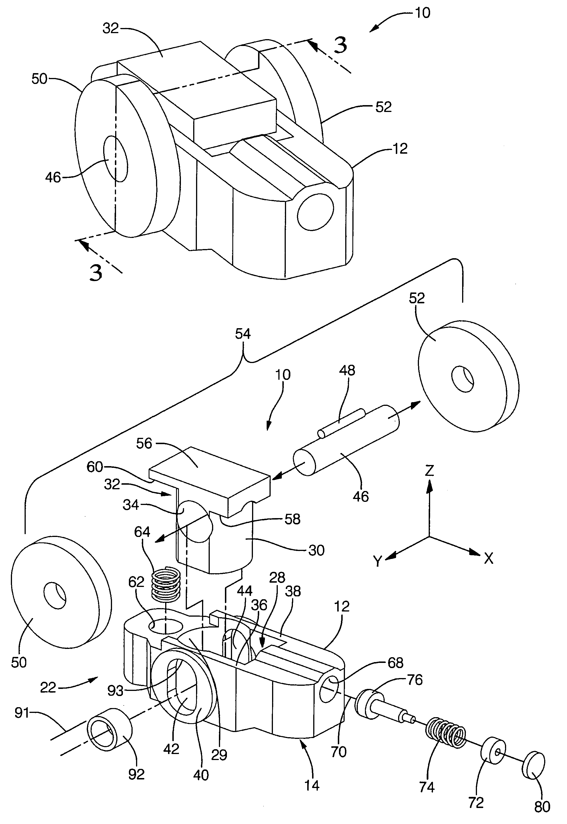
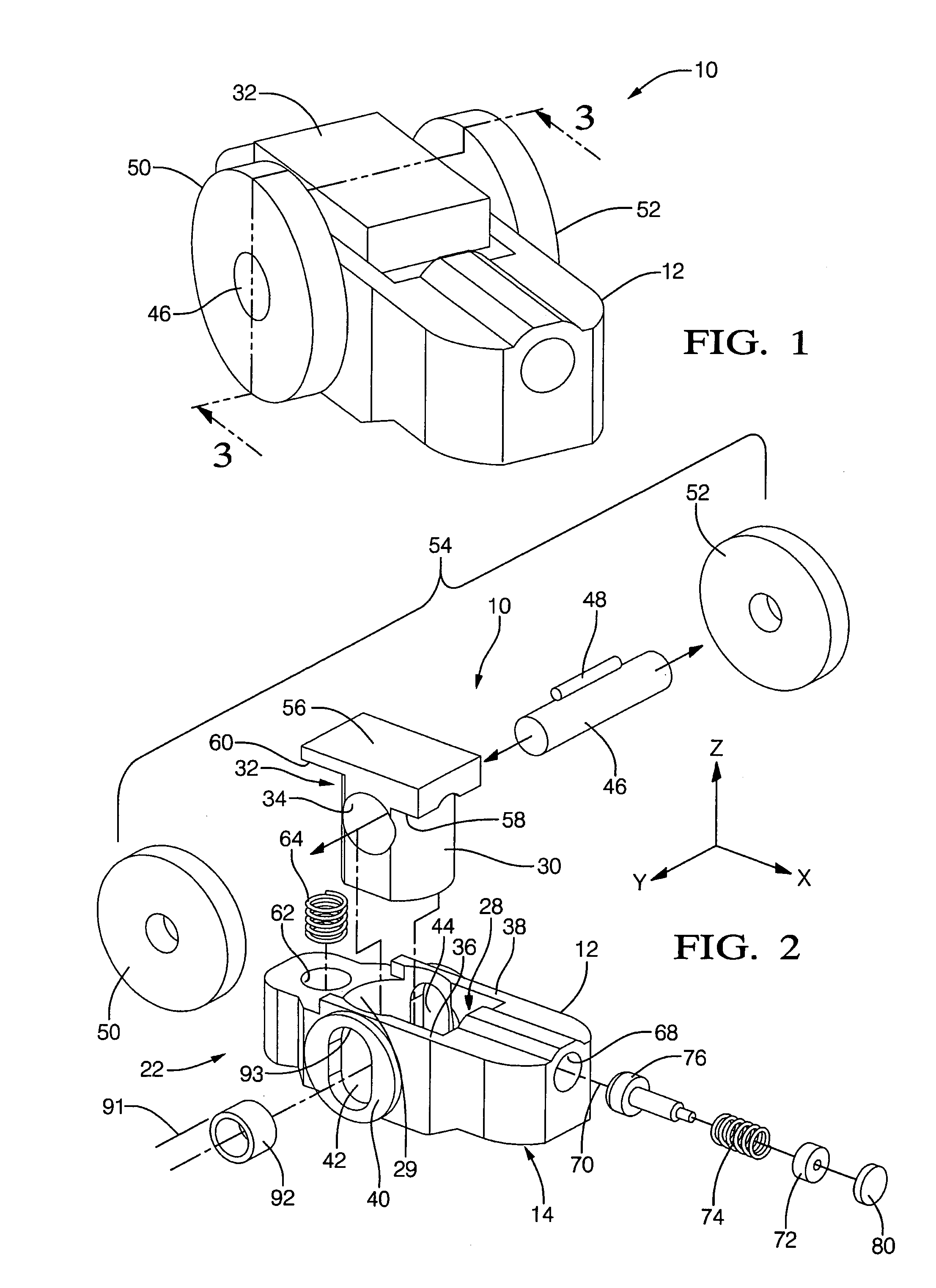
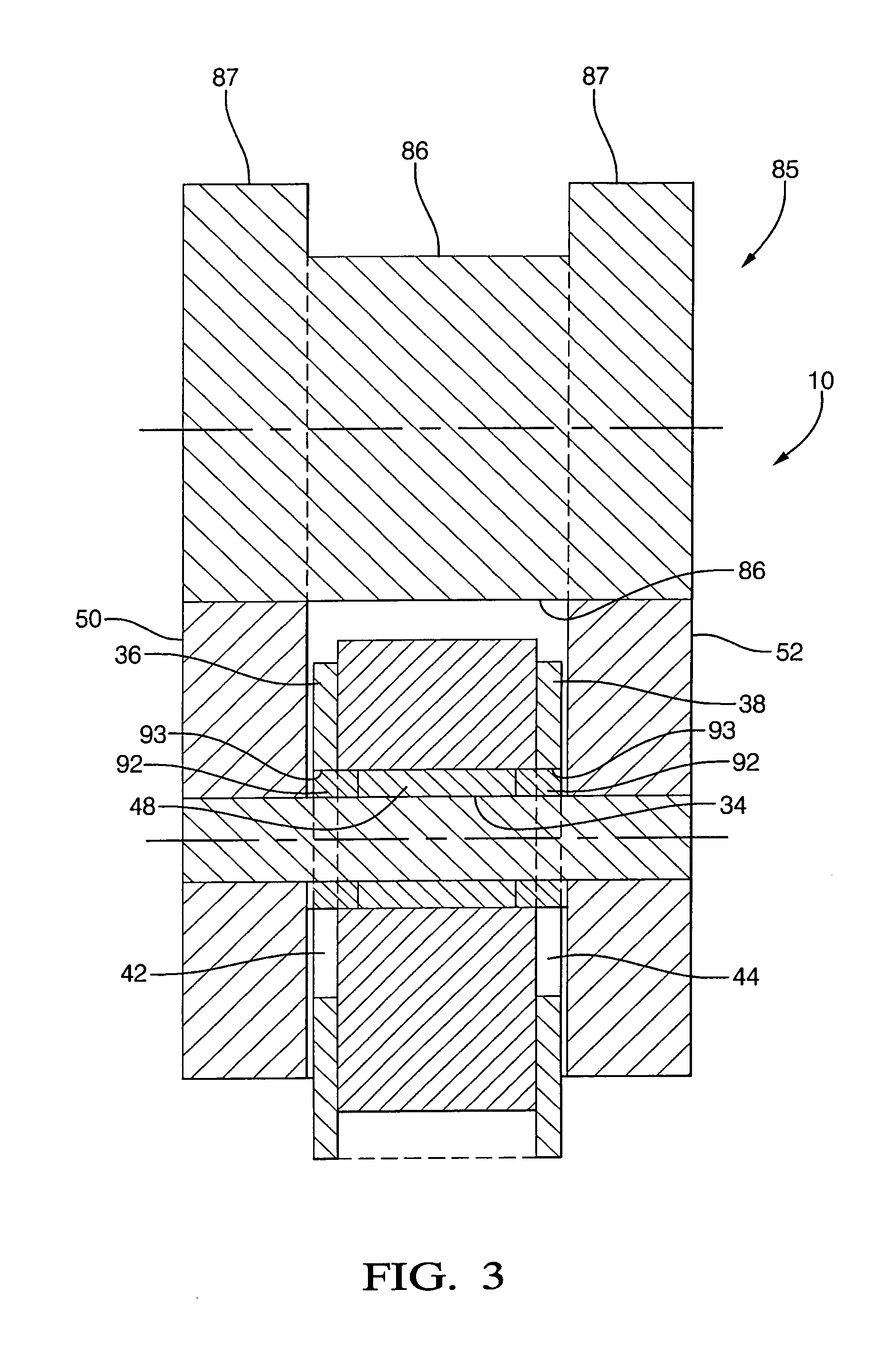
[0015]A roller finger follower assembly 10, 10′ for valve deactivation in accordance with the invention includes a follower body 12 having a first end 14 having means for receiving the head of a hydraulic lash adjuster 16 for pivotably mounting assembly 10, 10′ in an engine 18. The receiving means is preferably a spherical socket 20. A second and opposite end 22 of follower body 12 is provided with a pad 24, preferably arcuate, for interfacing with and actuating a valve stem 26 of an engine valve 27, such as a cylinder intake valve for engine 18. Body 12 is provided with a first passage 28 therethrough, passage 28 being generally cylindrical and having sliding surface 29 for slidably receiving a partially-cylindrical mating portion 30 of a reciprocating member 32 having a bore 34 transverse of passage 28. Passage 28 defines first and second body sidewalls 36,38. Sidewalls 36,38 are provided with flat bosses 40 on the outer surfaces, and elongated openings 42,44 are formed in the sid...


PUM


Abstract

A roller finger follower rocker arm assembly for deactivating an engine valve. A follower body pivots on a hydraulic lash adjuster, and engages a valve stem or lifter. The body receives a reciprocating member having a first and second rollers outboard of the body for following eccentrics of a cam lobe that straddles the body, the body having elongate openings on either side of the reciprocating member. A locking pin selectively locks and unlocks the body to the reciprocating member. The reciprocating member does not make contact with the cam lobe and functions only as a link between the latching mechanism and the rollers. The pin engages the reciprocating member by a latching spring and is disengaged by pressurized oil supplied through the hydraulic lash adjuster. Means is provided for limiting axial growth of the HLA during deactivation mode of the rocker arm assembly.

Description

TECHNICAL FIELD[0001]The present invention relates to mechanisms for altering the actuation of valves in internal combustion engines; more particularly, to finger follower type rocker arm assemblies having means for changing between normal and no valve lifts; and most particularly, to a two-step roller finger follower (RFF) assembly having a center reciprocating member disposed in a finger follower rocker arm body for reciprocating motion in the direction of lift between normal-lift and no-lift positions, and having a latching mechanism operative in an orthogonal bore in the finger follower body for latching and unlatching the reciprocating member to and from the finger follower body to shift between high lift and no lift modes, the latching mechanism being actuated by a latching spring and deactuated by engine oil supplied through a hydraulic lash adjuster.BACKGROUND OF THE INVENTION[0002]Variable valve activation mechanisms for internal combustion engines are well known. It is kno...

Claims


Application Information

Patent Timeline
Patent Type & Authority Patents(United States)
IPC IPC(8): F01L1/34F01L1/18F01L13/00
CPCF01L1/18F01L13/0005Y10T74/2107
Inventor HENDRIKSMA, NICK J.KUNZ, TIMOTHY W.
Owner DELPHI TECH INC
Learn More