
Polymeric restraints for containing an anode in an electrolytic capacitor from high shock and vibration conditions

a polymer and anode technology, applied in the field of capacitors, can solve the problems of capacitor failure, capacitor failure, severe stress force to a capacitor, etc., and achieve the effect of improving the reliability and safety of capacitors

Active Publication Date: 2006-08-15
WILSON GREATBATCH LTD
View PDF24 Cites 58 Cited by
  • Summary
  • Abstract
  • Description
  • Claims
  • Application Information

AI Technical Summary

Benefits of technology

[0002]Capacitors are used frequently in applications where high shock and vibration levels are experienced. A notable example is in the oil and gas industry where “measurement while drilling” applications can cause severe stress forces to a capacitor. Under high shock and vibration conditions, capacitors without adequate stabilization are capable of failing due to movement of the electrodes within the case, for example the anode pellet in an electrolytic capacitor. This movement can result in mechanical failure of the anode pellet lead rendering the capacitor inoperative. In that respect, mechanical stabilization of the anode pellet inside the casing is important for improving the reliability and safety of capacitors subjected to high shock and vibration conditions.

Problems solved by technology

A notable example is in the oil and gas industry where “measurement while drilling” applications can cause severe stress forces to a capacitor.
Under high shock and vibration conditions, capacitors without adequate stabilization are capable of failing due to movement of the electrodes within the case, for example the anode pellet in an electrolytic capacitor.
This movement can result in mechanical failure of the anode pellet lead rendering the capacitor inoperative.

Method used


Image

  • Polymeric restraints for containing an anode in an electrolytic capacitor from high shock and vibration conditions
  • Polymeric restraints for containing an anode in an electrolytic capacitor from high shock and vibration conditions
  • Polymeric restraints for containing an anode in an electrolytic capacitor from high shock and vibration conditions

Examples


Embodiment Construction

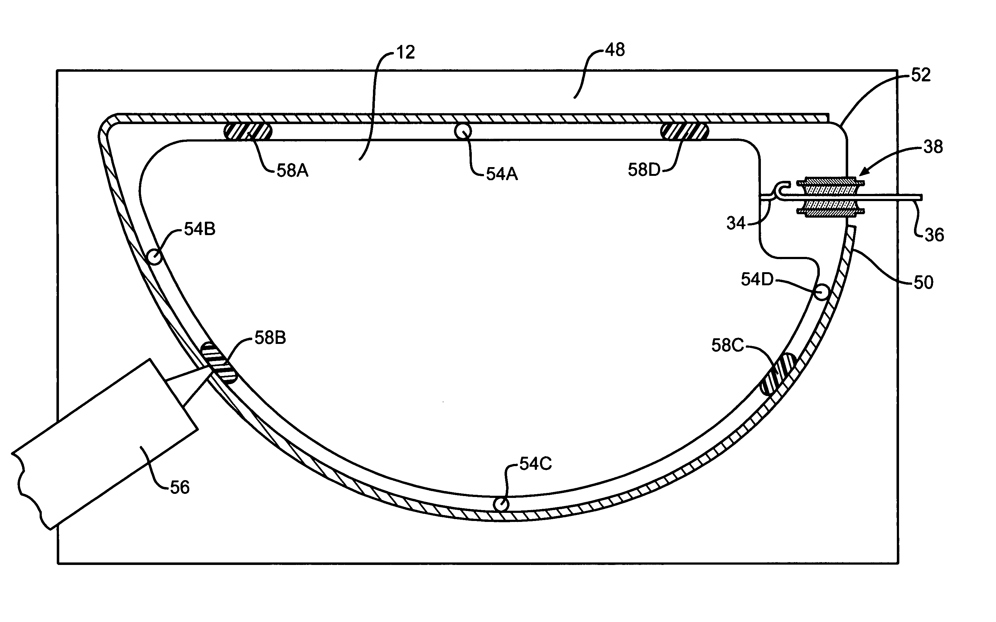
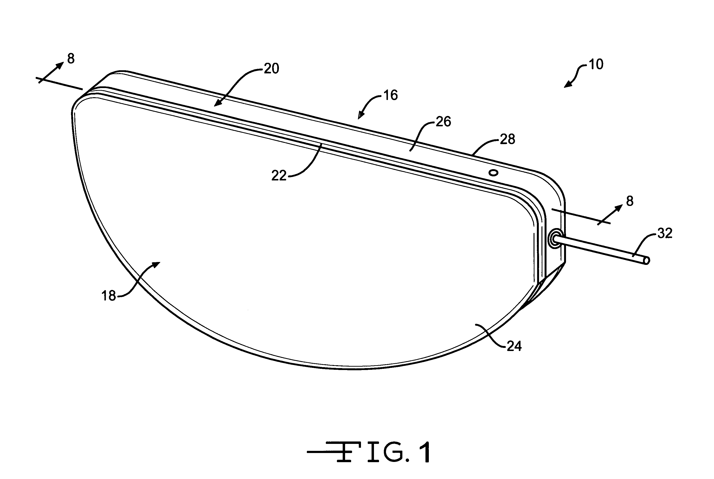
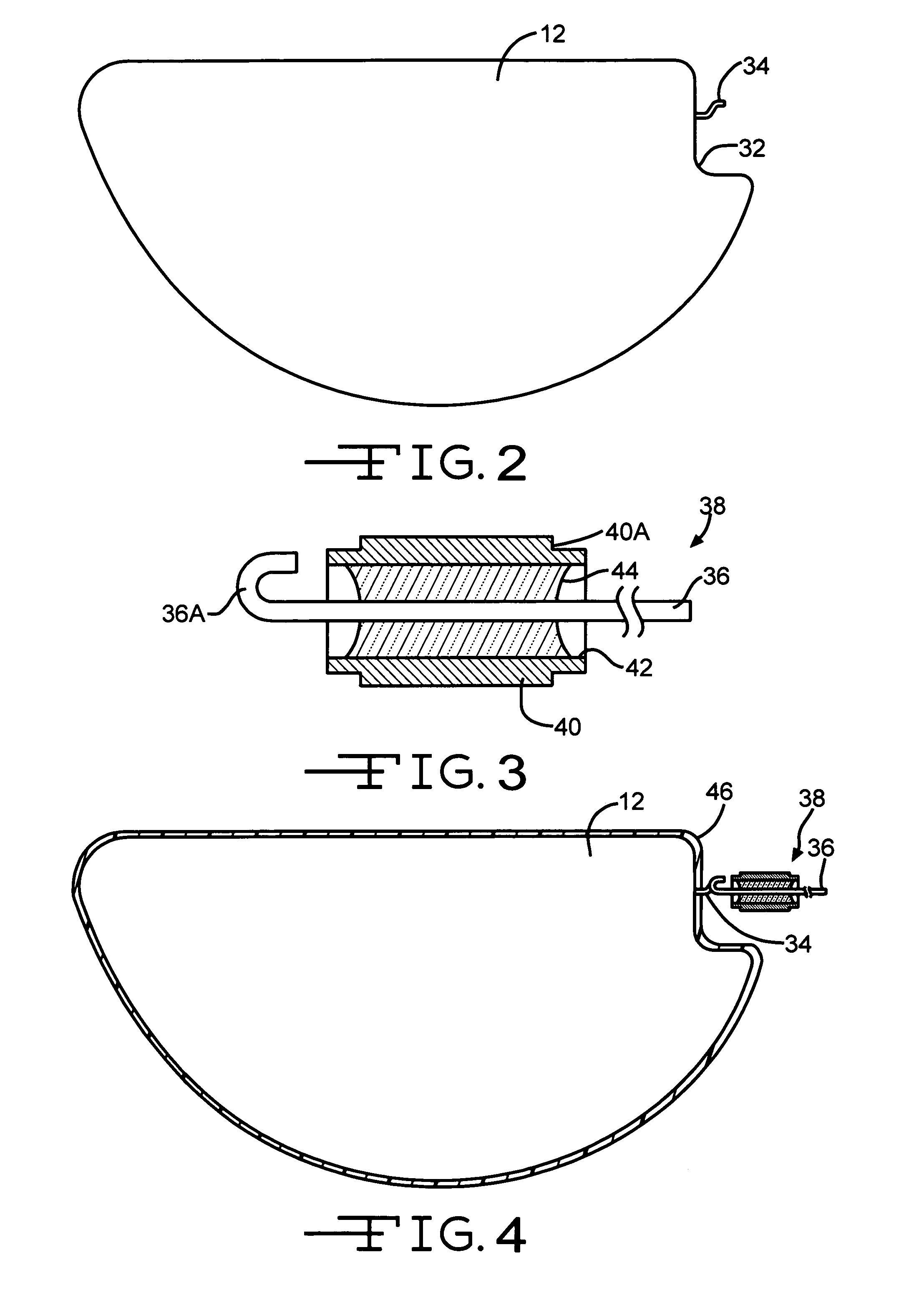
[0020]Referring now to the drawings, FIG. 1 is a perspective view showing a capacitor 10 according to the present invention. The capacitor 10 comprises an anode 12 (FIG. 2) of an anode active material and a cathode of a cathode active material 14 (FIG. 7) housed inside a hermetically sealed casing 16. The capacitor electrodes are operatively associated with each other by a working electrolyte (not shown) contained inside the casing, as will be described in detail hereinafter. The capacitor 10 is of an electrolytic type with the cathode comprising a conductive substrate having capacitive properties.

[0021]As particularly shown in FIGS. 1, 7 to 9 and 13, the casing 16 is of a metal material comprising first and second casing portions 18 and 20. Casing portion 18 comprises a surrounding sidewall 22 extending to a face wall 24. Similarly, casing portion 20 comprises a surrounding sidewall 26 extending to a face wall 28. Sidewall 26 is sized so that sidewall 22 is in an overlapping relati...


PUM

PropertyMeasurementUnit
Polymericaaaaaaaaaa

Abstract

An electrolytic capacitor comprising a plurality of polymeric structures molded about the periphery of the anode pellet is described. The polymeric structures contact between a weld strap surrounding the butt seam between matingclamshell” casing portions and the anode pellet sidewall. That way, the anode pellet is restrained from moving along both an x- and y-axes inside the casing. Having the cathode active material contacting the opposed major casing sidewalls being in a closely spaced relationship with the anode pellet through an intermediate separator prevents movement along the z-axis. The resulting capacitor is particularly well suited for use in high shock and vibration conditions.

Description

BACKGROUND OF THE INVENTION[0001]The present invention generally relates to a capacitor and, more particularly, to a capacitor capable of being subjected to high shock and vibration forces without failing.SUMMARY OF THE INVENTION[0002]Capacitors are used frequently in applications where high shock and vibration levels are experienced. A notable example is in the oil and gas industry where “measurement while drilling” applications can cause severe stress forces to a capacitor. Under high shock and vibration conditions, capacitors without adequate stabilization are capable of failing due to movement of the electrodes within the case, for example the anode pellet in an electrolytic capacitor. This movement can result in mechanical failure of the anode pellet lead rendering the capacitor inoperative. In that respect, mechanical stabilization of the anode pellet inside the casing is important for improving the reliability and safety of capacitors subjected to high shock and vibration con...

Claims


Application Information

Patent Timeline
IPC IPC(8): H01G9/00
CPCH01G9/06H01G9/10H01G11/52Y10T29/417Y02E60/13
Inventor GLOSS, EDWARDSTRINGHAM, RODNEYDRUDING, J. MICHAELMUFFOLETTO, BARRY
Owner WILSON GREATBATCH LTD
Learn More