
Methods and systems for fast restoration in a mesh network of optical cross connects

a mesh network and network failure technology, applied in the field of methods and systems for quickly restoring communication after a mesh network failure, can solve the problems of inefficient communication vehicles of sonet rings, loss of commerce and other benefits for network subscribers, and significant loss of revenue for network owners, etc., to achieve cost-effective, efficient use of available resources, and communication restoration

Inactive Publication Date: 2006-08-08
AMERICAN TELEPHONE & TELEGRAPH CO
View PDF13 Cites 54 Cited by
  • Summary
  • Abstract
  • Description
  • Claims
  • Application Information

AI Technical Summary

Benefits of technology

[0006]By strategically requiring a restoration path to be node and span disjoint from the failed normal communication path, error detection circuitry need only be placed at the add / drop ports of the end nodes along the normal communication path where communication signals enter and exit a mesh network. By allowing the nodes in the restoration path to choose the channels in the transmission lines that carry the communication signal at the time of restoration, efficient use of available resources is gained. The result is a cost effective network that restores communication in times competitive to that of SONET rings.

Problems solved by technology

For example, the sudden failure of such a link can cause a significant loss in revenue for a network owner and loss of commerce and other benefits for the network subscribers.
While SONET rings can quickly restore a failed communication channel, SONET rings are inefficient communication vehicles compared to “mesh” network topologies.
However, fast restoration in an optical mesh network can require sophisticated error detection of the digital traffic somewhere in the network that can be very expensive.

Method used


Image

  • Methods and systems for fast restoration in a mesh network of optical cross connects
  • Methods and systems for fast restoration in a mesh network of optical cross connects
  • Methods and systems for fast restoration in a mesh network of optical cross connects

Examples


Embodiment Construction

[0015]Because of recent advances and subsequent, deployment of dense wavelength division multiplexing systems, a new network layer, known as the optical layer has emerged. Currently, Synchronous Optical Network (SONET) rings provide the primary technology for optical layer communication and restoration from network failures. The SONET standards are predefined standards especially designed for optical communication systems and are described in detail by the ANSI T1.105 documentation. While SONET rings can quickly restore a failed communication channel, SONET rings are inefficient communication vehicles compared to “mesh” network topologies.

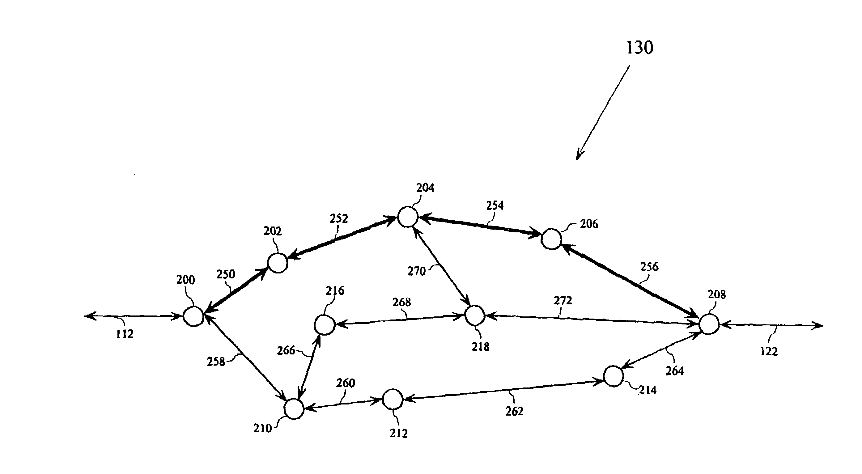
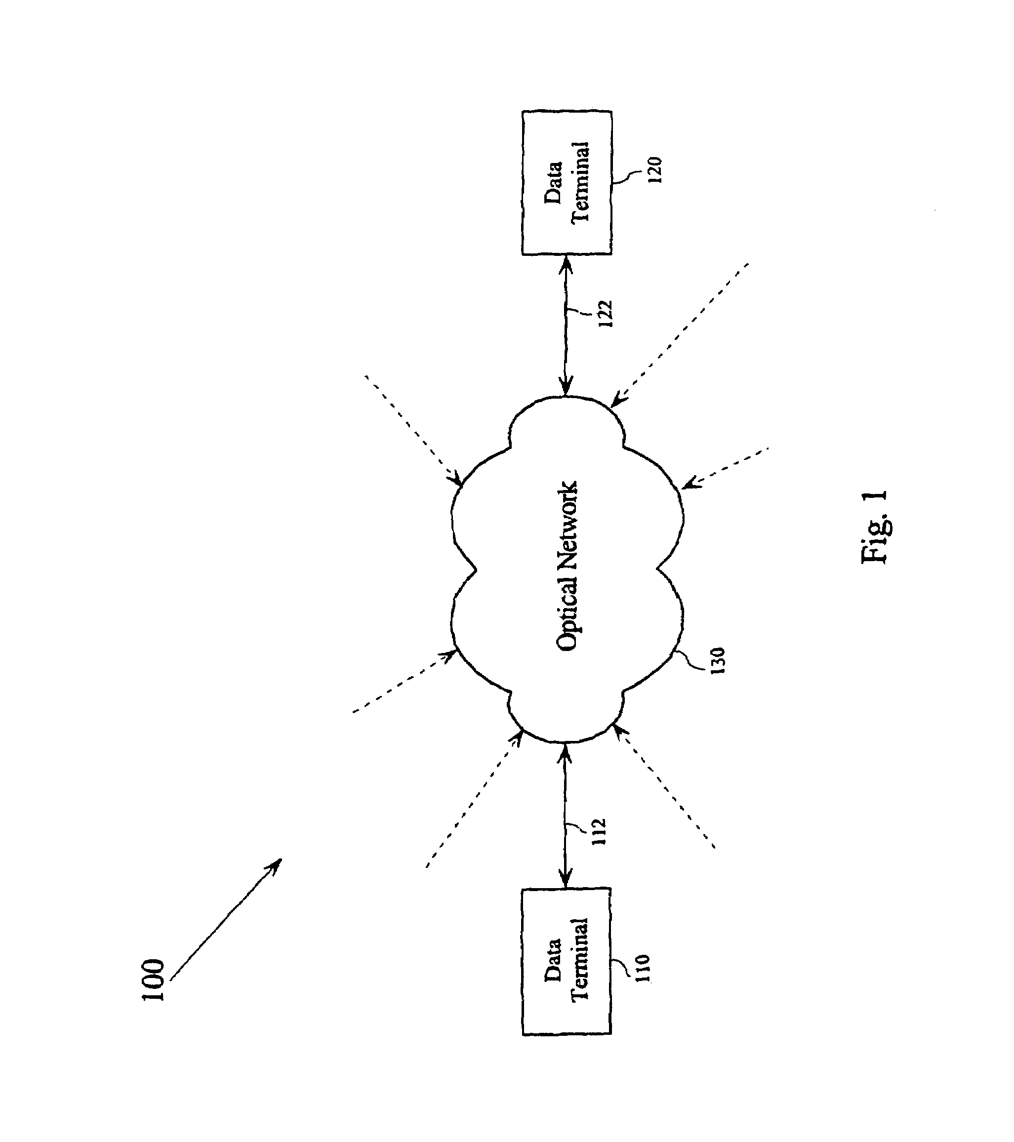
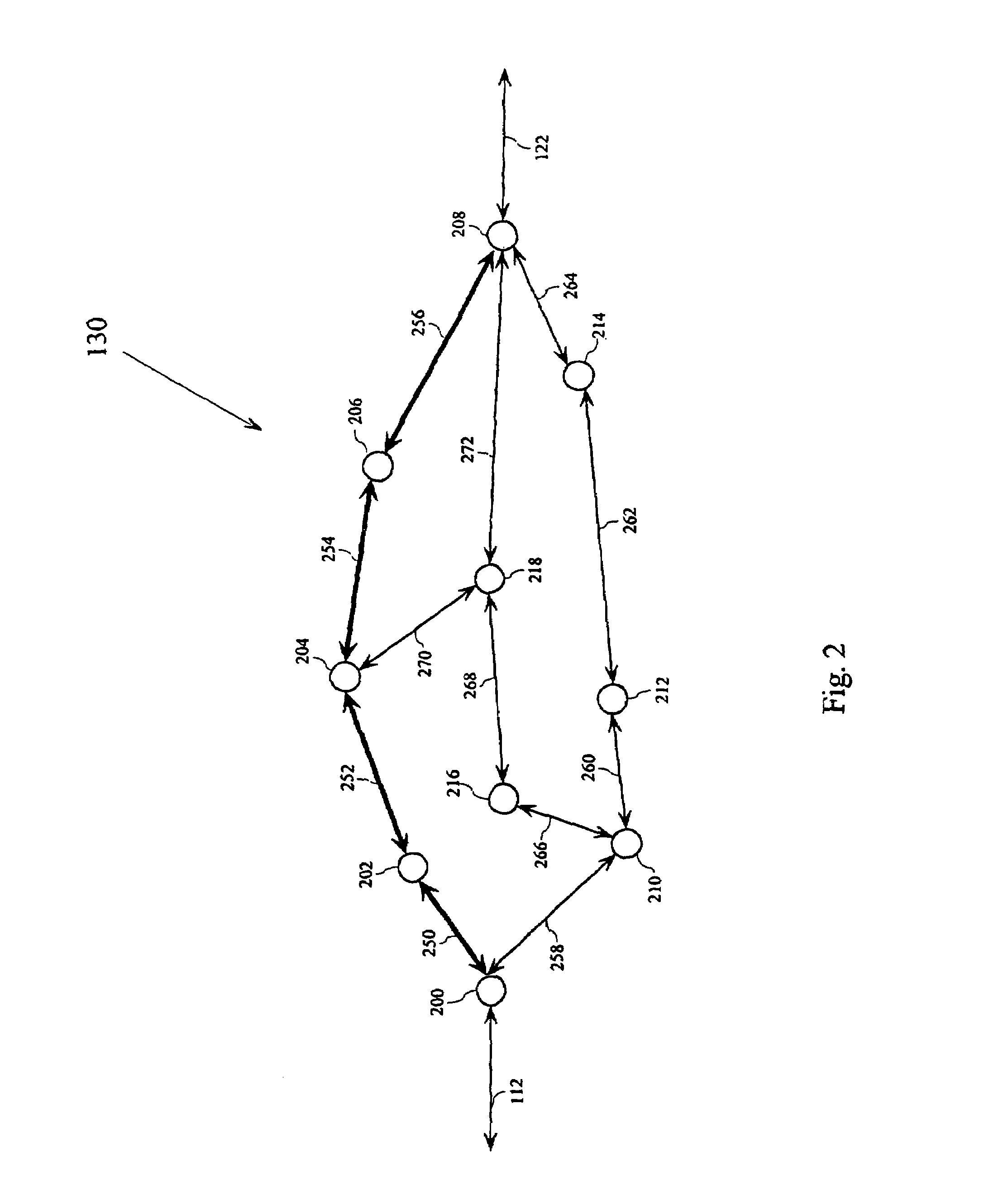
[0016]FIG. 1 shows an exemplary block diagram of a communication system 100. The communication system 100 includes a first data terminal 110 connected to an optical mesh network 130 through a first data link 112, and a second data terminal 120 connected to the optical mesh network 130 through a second data link 122. The optical mesh network 130 can...


PUM


Abstract

Communication is restored in a fiber optic network by placing error detection circuitry at the add / drop ports of the network nodes of the network. If the error detection circuitry detects an error condition for a communication signal traversing a normal communication path within the network, the communication signal is rerouted along a restoration communication path that is node and span disjoint from the first communication path. By requiring a restoration path to be node and span disjoint from the normal communication path, error detection circuitry need only be placed at the end nodes of the normal communication path. By allowing each node in the restoration path to dynamically choose the particular channels that can accommodate a particular communication signal at the time of the restoration, efficient use of available resources is gained. The result is a cost effective network that restores communication in times competitive to that of SONET rings.

Description

CROSS-REFERENCE TO RELATED APPLICATION[0001]This is a continuation of U.S. patent application Ser. No. 09 / 474,031 filed Dec. 28, 1999 now U.S. Pat. No. 6,970,417.BACKGROUND OF THE INVENTION[0002]This invention relates to methods and systems for quickly restoring communication after a failure in a mesh network.[0003]Modern communication networks serve to transport large volumes of information between a number of locations connected with the network. The communication network includes a set of nodes and links interconnecting each of the nodes to other nodes. The traffic across a link between two nodes in a communications network can represent a formidable volume of information flow. As a communication network carries more data, the failure of a single node or link within the network can have a greater impact. For example, the sudden failure of such a link can cause a significant loss in revenue for a network owner and loss of commerce and other benefits for the network subscribers.[00...

Claims


Application Information

Patent Timeline
Patent Type & Authority Patents(United States)
IPC IPC(8): H04J1/16H04J3/14G01R31/04H04J14/02
CPCH04J3/14H04J14/0228H04J14/0241H04J14/0284H04J14/0227H04J2203/006
Inventor DOVERSPIKE, ROBERT DUNCANSAHIN, GOKHANSTRAND, JOHN LESTERTKACH, ROBERT WILLIAM
Owner AMERICAN TELEPHONE & TELEGRAPH CO
Learn More