
Wavelength division multiplexed device

a multi-channel optical communication and wavelength division technology, applied in electromagnetic transmission, transmission monitoring/testing/fault-measurement systems, transmissions, etc., can solve the problems of increasing difficulty in multi-channel multi-multiplication or demultiplexing, non-uniform channel power, etc., and achieve the effect of advantageous use as a gain flattening filter

Inactive Publication Date: 2006-08-01
IBSEN PHOTONICS
View PDF28 Cites 27 Cited by
  • Summary
  • Abstract
  • Description
  • Claims
  • Application Information

AI Technical Summary

Benefits of technology

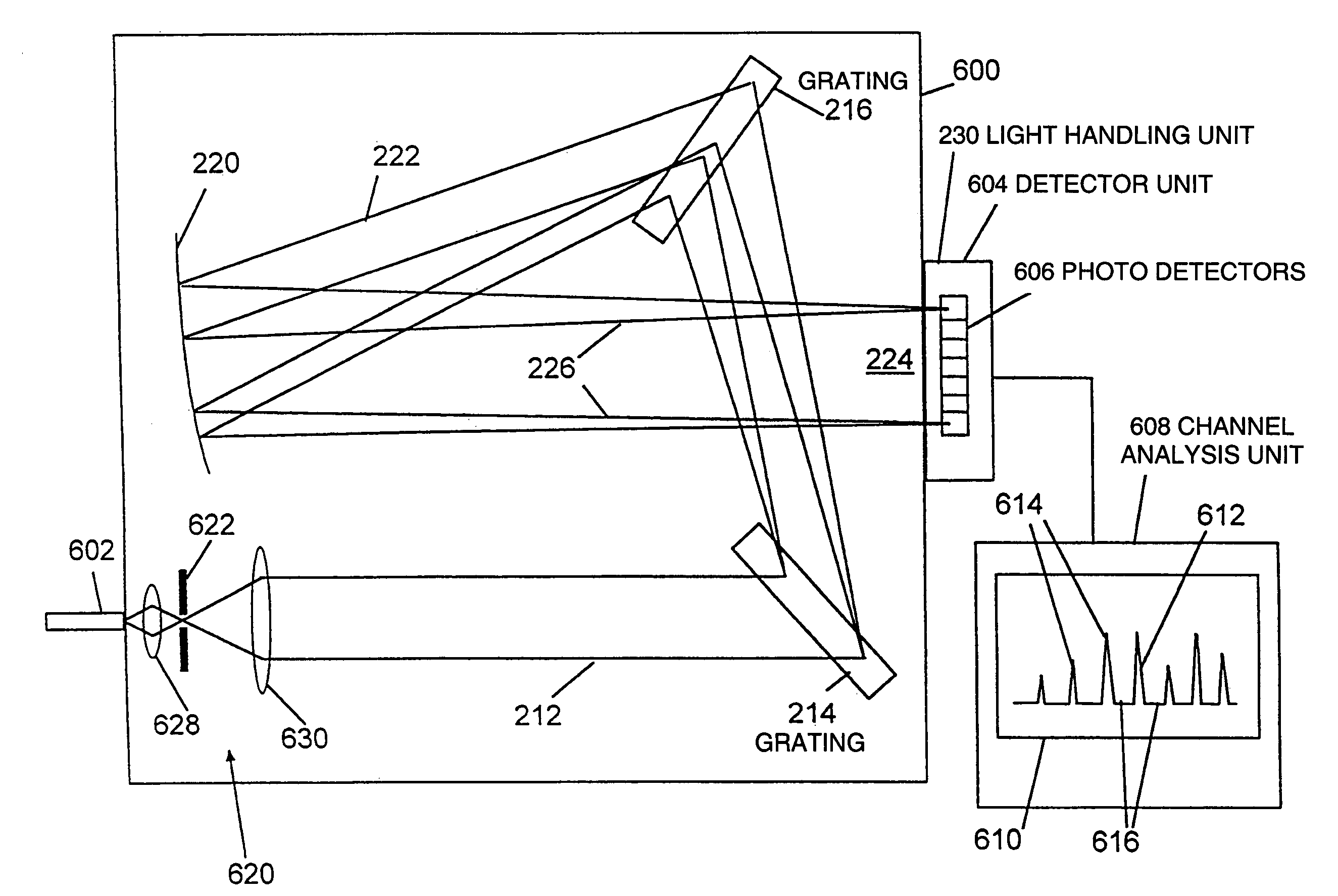
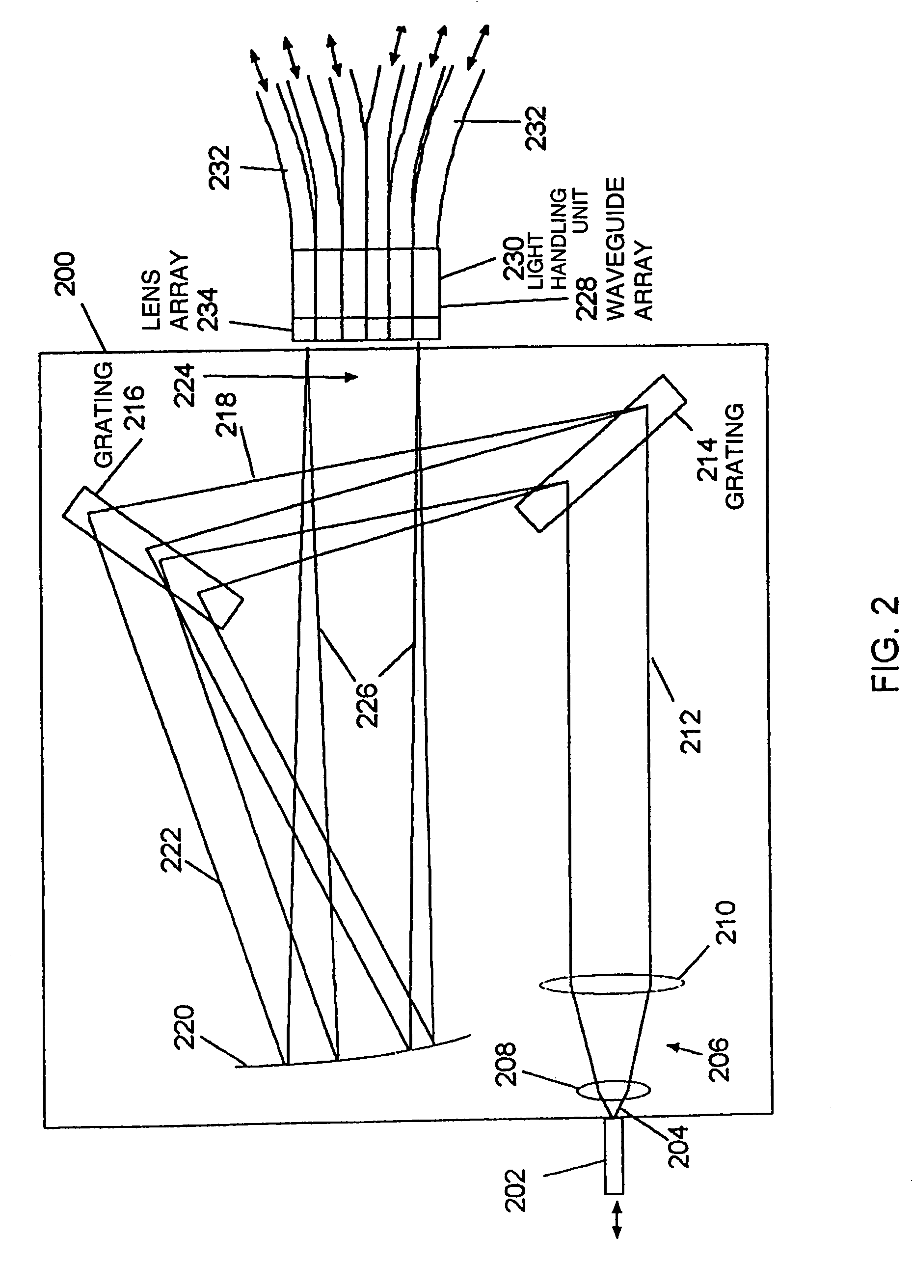
[0007]Generally, the present invention relates to a WDM device that is based on the use of at least two transmissive diffraction elements. The WDM device provides flexible use and may be widely applied in WDM systems. The device is useful for multiplexing and demultiplexing, channel monitoring, for adding and dropping channels, and for controlling the power in individual channels within a multiple channel signal. The device provides for dynamic control of individual channels, and may be advantageous in use as a gain flattening filter.

Problems solved by technology

However, it becomes increasingly difficult to multiplex or demultiplex the WDM channels when the frequency separation is smaller.
The transmission of a multiple channel signal along a fiber link often introduces wavelength dependent losses or gains, resulting in non-uniform channel power.

Method used


Image

  • Wavelength division multiplexed device
  • Wavelength division multiplexed device
  • Wavelength division multiplexed device

Examples


Embodiment Construction

[0054]The present invention is applicable to transmission grating spectrometers, and is believed to be particularly useful in dense wavelength division multiplexed (DWDM) applications for optical communications, particular controlling the power profile of a multiple channel optical communications signal.

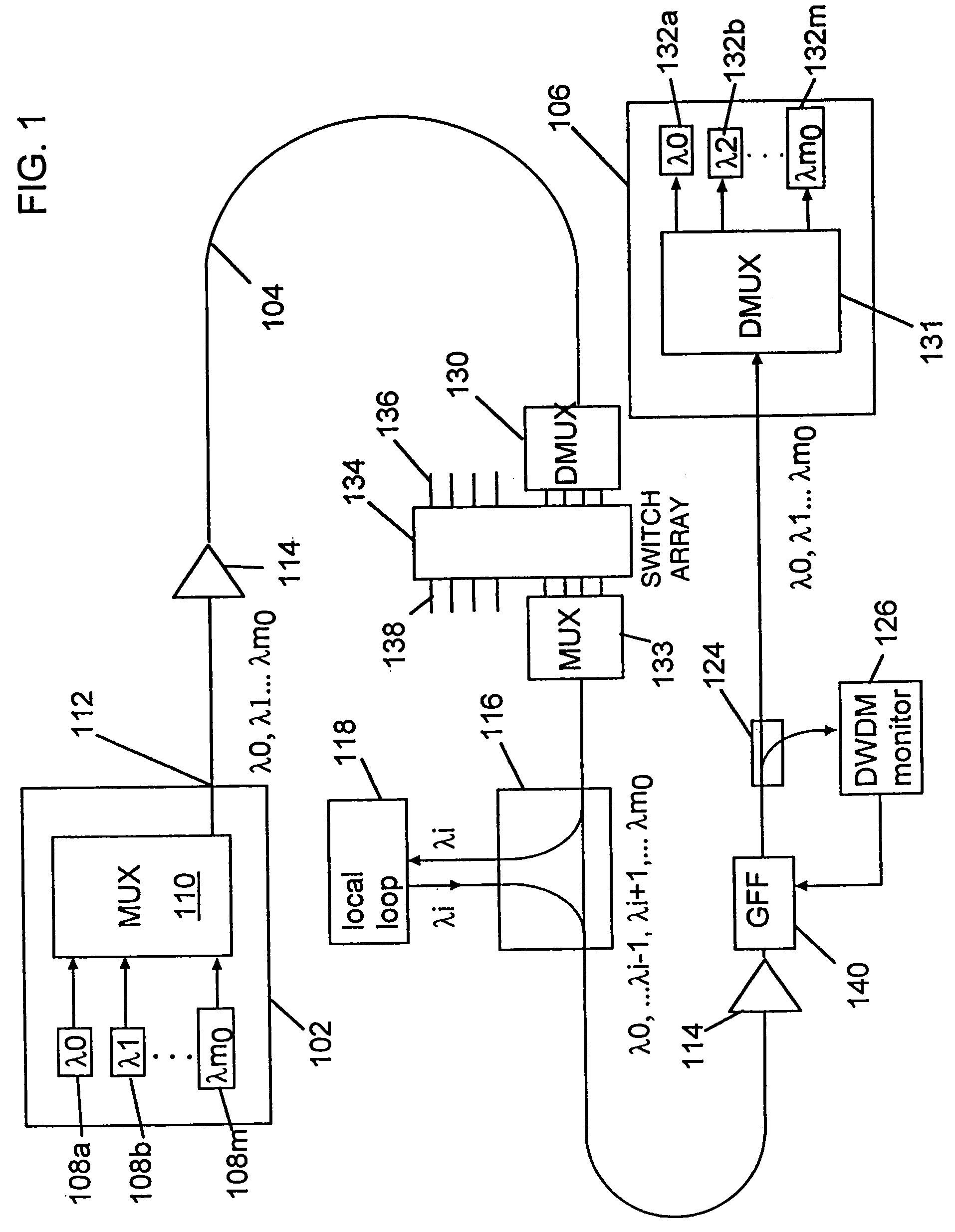
[0055]DWDM communications systems use several channels of light at different optical frequencies. According to the ITU standards, the channels are evenly spaced by frequency. Thus, the mth channel has a frequency given by vo+mΔv, where vo is a lowest channel frequency, Δv is the channel separation and m is an integer value ranging from 0 to m0, the upper value. The value of m0 may be any suitable number, for example 19, 39, 79, or higher. According to commonly used ITU standards, the channel separation, Δv, may be, amongst other values, 100 GHz or 50 GHz. In the following discussion, the different DWDM channels are described in terms of both frequency and wavelength. It will be appre...


PUM


Abstract

A wavelength division multiplexed device is based on a transmission grating spectrometer having at least two diffractive optical elements. The WDM device provides flexible use and may be widely applied in WDM systems. The device is useful for multiplexing and demultiplexing, channel monitoring, for adding and dropping channels, and for controlling the power in individual channels within a multiple channel signal. The device provides for dynamic control of individual channels, and may be advantageous in use as a gain flattening filter.

Description

FIELD OF THE INVENTION[0001]The present invention is directed to a device for use with multiple channel optical communications, and more particularly to a device that is useful for multiplexing / demultiplexing, channel monitoring, add / drop filtering and controlling the power profile of a multiple channel signal.BACKGROUND[0002]One of the advantages of optical fiber communication is the potential for large information handling capacity. One approach to increasing the optical bandwidth over which information is transmitted in an optical fiber is to use wavelength division multiplexing (WDM) or dense wavelength division multiplexing (DWDM), where light at several different wavelengths is combined and injected into a fiber, the light at each wavelength typically being independently modulated with information prior to combining with the other wavelengths. After propagation through the fiber, the light is then separated into its different wavelength components before detection.[0003]As use...

Claims


Application Information

Patent Timeline
Patent Type & Authority Patents(United States)
IPC IPC(8): H04B17/00G02B5/18G02B6/34H04J14/02
CPCG01J3/02G01J3/0213G01J3/0224G01J3/0256G01J3/0291G01J3/1804G02B6/272G02B6/29311G02B6/29313G02B6/2938G01J3/0208H04J14/0221G01J3/08G02B6/2773G02B2005/1804H04J14/02216
Inventor IBSEN, PER ELDPEDERSEN, CLAUS FRIIS
Owner IBSEN PHOTONICS
Learn More