
System and method for a multi-frequency upstream channel in a computer network

a multi-frequency upstream channel and computer network technology, applied in the field of communication in computer networks, can solve the problems of inefficient embodiment, high cost, and inability to meet the unique characteristics and requirements of other types of systems

Inactive Publication Date: 2006-08-01
HEWLETT PACKARD DEV CO LP
View PDF157 Cites 61 Cited by
  • Summary
  • Abstract
  • Description
  • Claims
  • Application Information

AI Technical Summary

Benefits of technology

The patent describes a system and method for providing a multi-frequency upstream transmission channel for a network device. The system receives a first message from a headend network entity with multiple upstream frequencies allocated for upstream transmission. The network device uses a predetermined frequency hopping algorithm or time pattern to determine which frequency to use for upstream transmission. During the next upstream burst, the network device employs the same algorithm or time pattern to determine a new upstream frequency. The system can also receive a second message from the headend network entity with new or different upstream frequencies or a new frequency hopping descriptor. This allows for flexibility and adaptability in the event of frequency impairment. Overall, the system provides a more robust and reliable communication network.

Problems solved by technology

However, because the DOCSIS was designed for cable television systems, it is inadequate to address some unique characteristics and requirements of other types of systems such as the wireless system.
However, such an embodiment is not efficient and very expensive since having the antenna diversity on a client device can double the cost of this equipment in every home deployment.

Method used


Image

  • System and method for a multi-frequency upstream channel in a computer network
  • System and method for a multi-frequency upstream channel in a computer network
  • System and method for a multi-frequency upstream channel in a computer network

Examples


Embodiment Construction

Exemplary Data-Over-Cable System

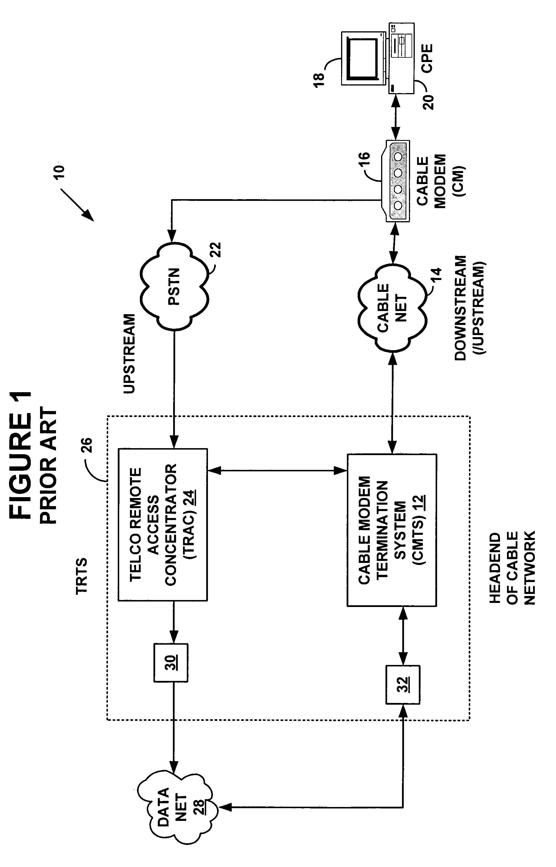
[0029]FIG. 1 is a block diagram illustrating an exemplary data-over-cable system 10. The data-over-cable system 10 may be a bi-directional cable system supporting a downstream data flow and an upstream data flow to and from a cable television network “headend” from and to a customer premises equipment entity such as a personal computer, for instance. The cable television network “headend” is a central location responsible for sending cable signals in a downstream and an upstream direction. In a bi-directional cable system, customer premises equipment entities or a cable modem may have an upstream connection to a cable modem termination system via a cable television connection, a wireless connection, a satellite connection or a different connection by which the cable modem may send data upstream to the cable modem termination system.

[0030]Alternatively, the data-over-cable system 10 may be a uni-directional cable system supporting only a downstream dat...


PUM


Abstract

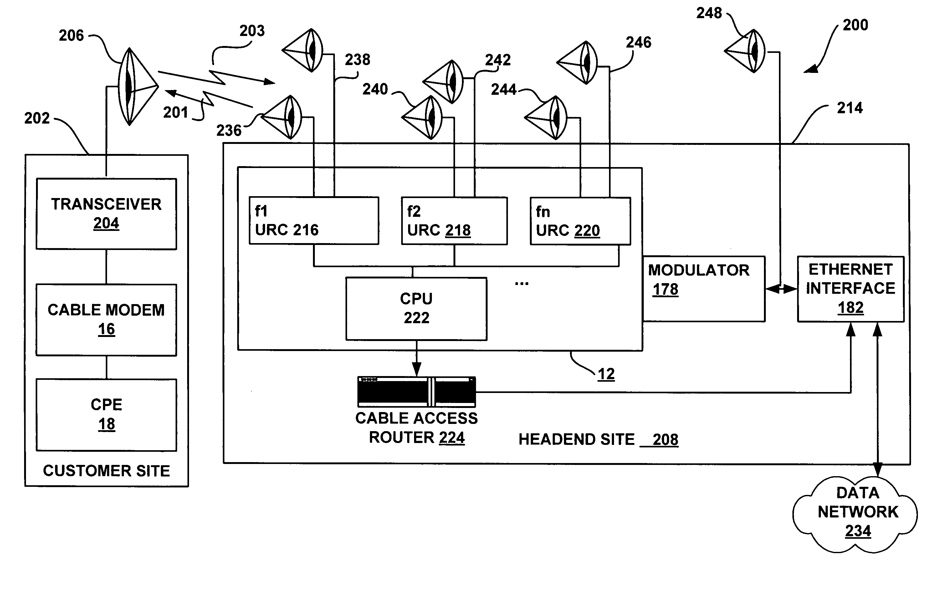
System and method for providing a multi-frequency upstream transmission channel to a network device. When a headend network entity generates an upstream channel descriptor message, the descriptor message includes at least two upstream frequencies available for upstream transmission, and a frequency hopping descriptor with a frequency-hopping pattern associated with the available frequencies for determining an upstream frequency for upstream transmission. The headend provides a timing reference for determining upstream transmission periods on the frequencies available on the network device. When the headend receives upstream transmission on one of the available upstream frequencies, the headend network entity determines frequency distortions. If the distortions exceed a threshold level, the headend may send a new upstream channel descriptor message that excludes the upstream frequency associated with the high frequency distortions, add a new upstream frequency, or defines a new frequency-hopping pattern.

Description

FIELD OF THE INVENTION[0001]The present invention relates to communications in computer networks. More particularly, it relates to a method and a system for a more robust upstream path within a currently existing data-over-cable framework.BACKGROUND OF THE INVENTION[0002]Cable television networks such as those provided by Comcast Cable Communications, Inc., of Philadelphia, Pa., Cox Communications of Atlanta Ga., Time-Warner Cable, of Marietta Ga., Continental Cablevision, Inc., of Boston Mass., and others, provide cable television services to a large number of subscribers over a large geographical area. The cable television networks are typically interconnected by cables such as coaxial cables or a Hybrid Fiber / Coaxial (“HFC”) cable system that have data rates of about 10 Mega-bits-per-second (“Mbps”) to 30+ Mbps.[0003]The Internet, a world-wide-network of interconnected computers, provides multi-media content including audio, video, graphics and text that require a large bandwidth...

Claims


Application Information

Patent Timeline
Patent Type & Authority Patents(United States)
IPC IPC(8): H04B1/713
CPCH04B1/715H04N21/2385H04N7/165H04B7/12H04B2001/7154H04N21/2408
Inventor VOLDMAN, MIKHAILBUDINGER, DANAKGUN, ALIFIJOLEK, JOHN G.VOGEL, MARK O.KELKAR, KRIS
Owner HEWLETT PACKARD DEV CO LP
Learn More