Standardized rotary actuator

Active Publication Date: 2006-07-25
FATHOM5 CORP
View PDF122 Cites 22 Cited by
  • Summary
  • Abstract
  • Description
  • Claims
  • Application Information

AI Technical Summary

Benefits of technology

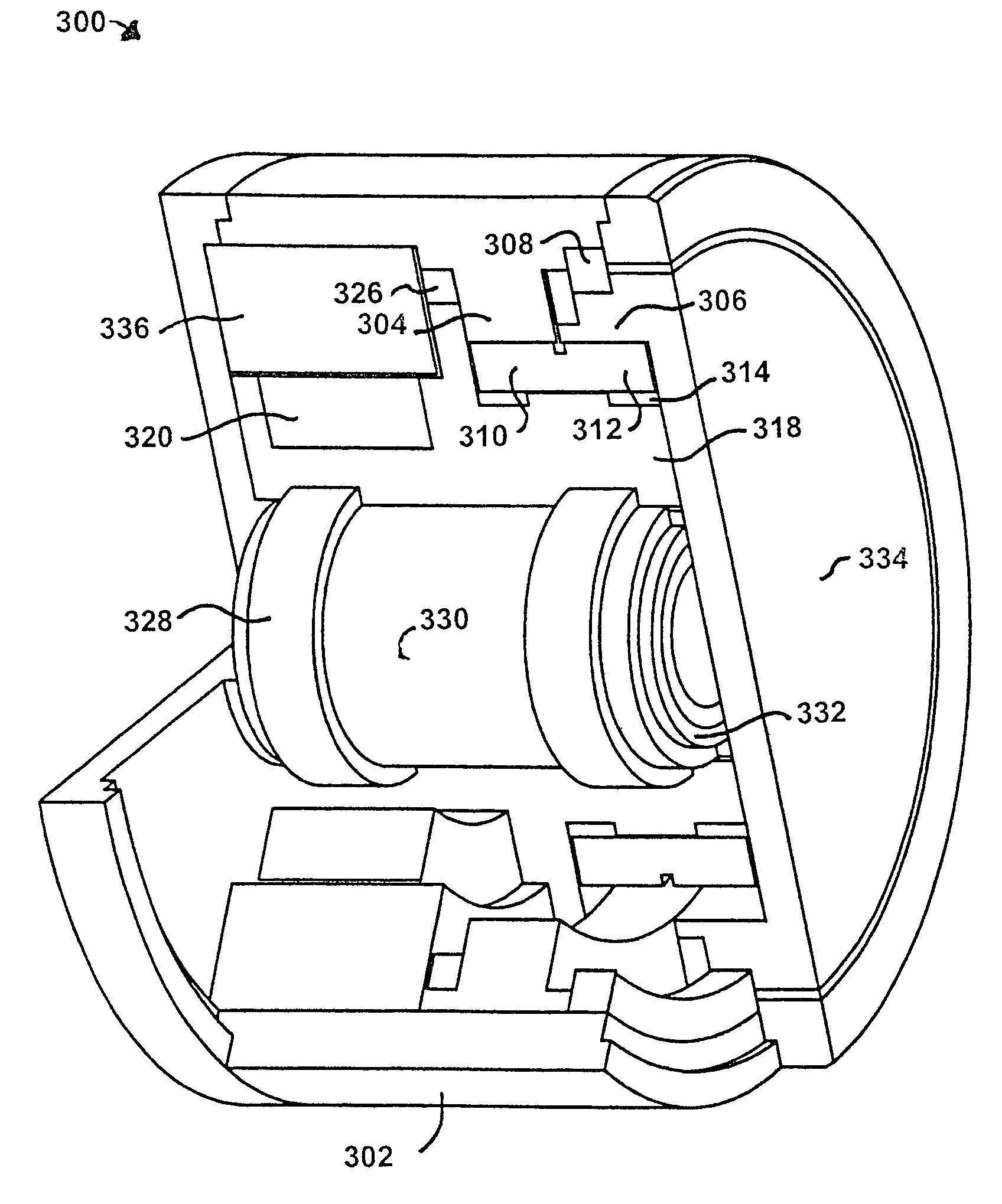
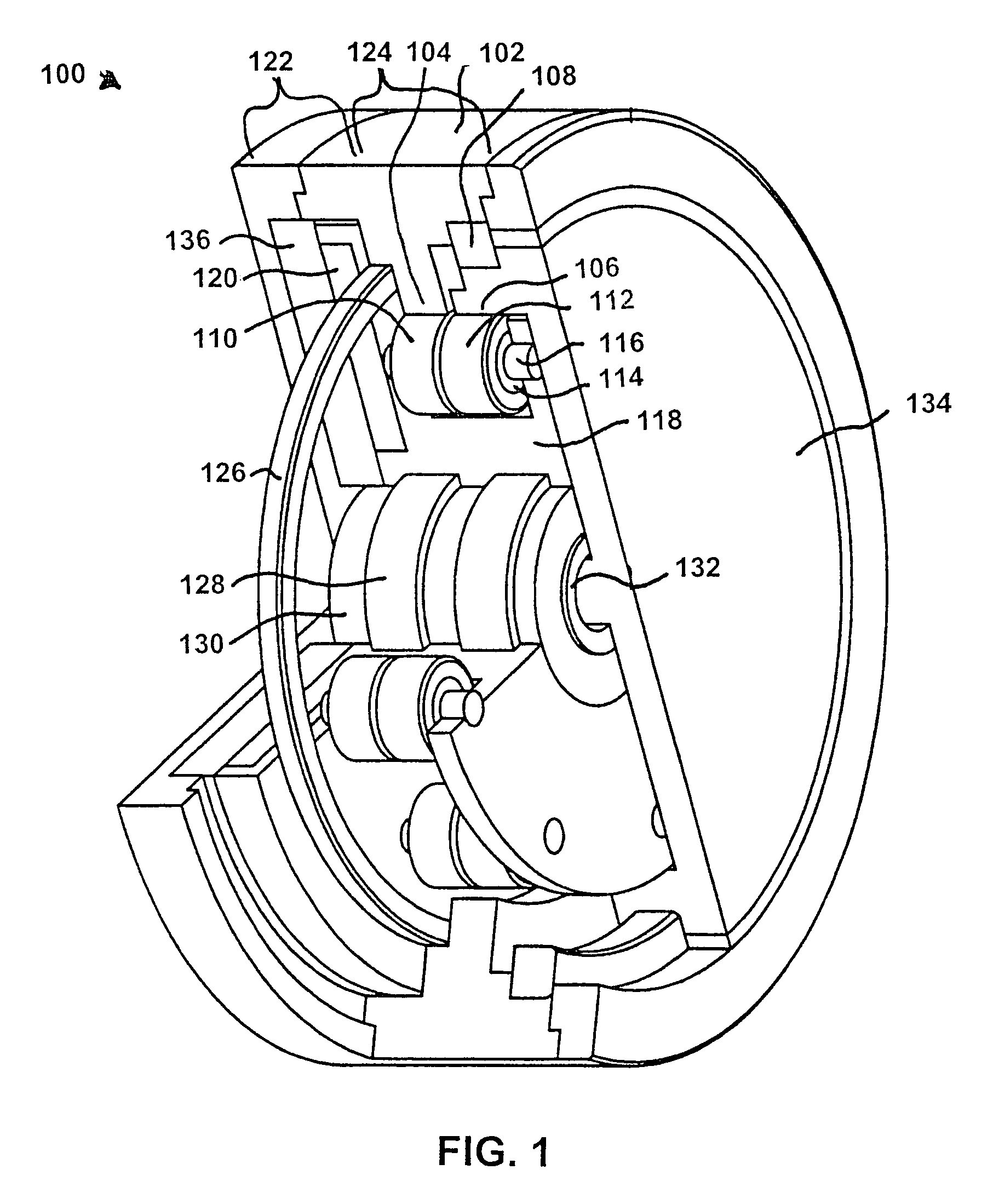
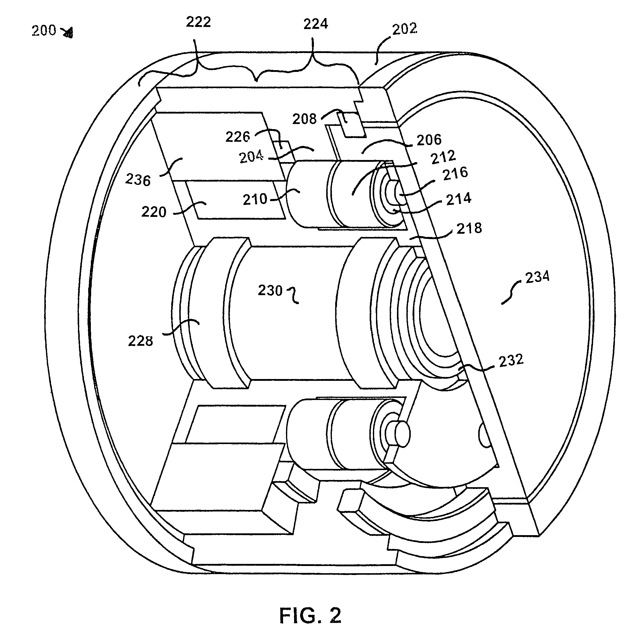
[0014]As discussed above, automated mechanical systems are generally custom, one-off systems designed essentially from the ground up. The inventor of the standardized rotary actuator module described herein believes that the level of custom engineering required for the implementation of a motion control system can be drastically reduced through the development and use of standardized modules of the type described herein.
[0017]In certain embodiments, the rotary actuator modules of the present invention may be produced in standardized geometries and sizes. An appropriate set of standardized sizes facilitates the standardization of machine architecture accordingly. This standardization enables the machine designer to assemble or reconfigure machines on demand, in a similar manner to that employed presently for the configuration of personal computers. The use of standards enables the diffusion of new technology, tending to increase performance while decreasing costs.
[0018]One object of the present invention is to create a standardized rotary actuator which can be mass produced at low cost, low weight and low volume, and still maintain a high level of performance. Various levels of ruggedness—for example, light, medium, and heavy—may be developed for various applications.
[0019]The present invention is a new high-performance rotary actuator in a variety of embodiments sharing certain characteristic features. In general, a high level of performance can be preserved even for low cost versions of the present invention. Depending on the application, each of the embodiments incorporates features generating one or more of certain advantages.
[0020]The novel design of certain embodiments of the present invention provide simplicity of design using a minimal number of parts and a minimized list of parameters, thereby allowing for a relatively small form factor exhibiting exceptional compactness, stiffness and load capacity, along with quiet and efficient operation. They can be designed for easy assembly, ideal for mass production at various quality levels.
[0022]The rotary actuators described herein have the potential to be more compact, simpler, more easily assembled and less expensive than any rotary actuator developed before. These devices may also be configured to exhibit lower inertia and provide higher stiffness than any rotary actuator developed before.

Problems solved by technology

This one-off design methodology tends to result in systems exhibiting relatively high cost and a low rate of change and diffusion of new technology.
Another undesirable effect of custom mechanical design methodology is rapid obsolescence.
In general, operator interfaces are cumbersome, maintenance training is complex, and the logistics trail for maintenance is a permanent and expensive user obligation.
Often, the designer of an automated mechanical system is first faced with the design of a machine joint, which, owing to the relative absence of standardized machine joint solutions, must be performed beginning from basic structural components, such as plates, beams, and bearings.
Although certain components may be designed to interface with the related components, a relatively high degree of engineering effort must still be exerted to ensure that the various components will work together properly under a variety of operating conditions.
Modules incorporating both a prime mover and a gear train are known as “gearmotors” or “gearhead motors.” Although somewhat successful, this integration has suffered from the use of inadequate gear train designs, thereby limiting the overall effectiveness of such modules.
These designs use pins through the plates to transmit torque to the output plate, adding a further level of complexity and a number of dimensions having critical tolerances.
They do, but no one has heretofore found a satisfactory means to get that high torque to a concentric rotating output shaft.
The force path for these devices between input and output is long and circuitous, requiring a large, and very heavy, hoop structure to keep all the forces contained.
All of this adds considerably to the compliance and lack of rigidity of the gear train.
Because of their unique geometry, complexity, volume and weight, these gear trains are very difficult to integrate into self-contained actuator modules.

Method used


Image

  • Standardized rotary actuator
  • Standardized rotary actuator
  • Standardized rotary actuator

Examples


Embodiment Construction

[0041]While the making and using of various embodiments of the present invention are discussed in detail below, it should be appreciated that the present invention provides many applicable inventive concepts, which can be embodied in a wide variety of specific contexts. The specific embodiments discussed herein are merely illustrative of specific ways to make and use the invention and do not delimit the scope of the invention.

[0042]Certain embodiments of the present invention are standardized rotary actuators which can be mass produced at low cost and still maintain a high level of performance. Various levels of ruggedness—for example, light, medium, and heavy—may be employed for various applications. In fact, certain of the actuator concepts described herein will be found sufficiently rugged in their basic design that parts made of plastic or formed metal can be used to reduce cost while still providing a highly-versatile actuator useful in a variety of applications. These applicat...


PUM


Abstract

A rotary actuator incorporating a shell, an output plate and a cross-roller bearing retaining the output plate within the shell. A prime mover, disposed within the shell, exerts torque on a gear train within the shell. A pair of gears, disposed on either side of the cross-roller bearing, mesh with one or more gears in the geartrain. Depending on the application, the geartrain may be a planetary epicyclic or an eccentric hypocyclic type.

Description

CROSS REFERENCE TO RELATED APPLICATION[0001]This application claims the priority of U.S. Provisional Patent Application Ser. No. 60 / 429,276, filed Nov. 25, 2002.TECHNICAL FIELD OF THE INVENTION[0002]The present invention relates in general to rotary power devices, and specifically to rotary actuators for use in automated machinery.BACKGROUND OF THE INVENTION[0003]Most automated mechanical systems developed today are built as unique custom one-off systems employing little or no standardized architecture. This one-off design methodology tends to result in systems exhibiting relatively high cost and a low rate of change and diffusion of new technology.[0004]Another undesirable effect of custom mechanical design methodology is rapid obsolescence. In general, operator interfaces are cumbersome, maintenance training is complex, and the logistics trail for maintenance is a permanent and expensive user obligation.[0005]Often, the designer of an automated mechanical system is first faced wit...

Claims


Application Information

Patent Timeline
IPC IPC(8): F16H23/00F16H1/32F16H59/00B64C13/34F16H1/28F16H1/46F16H57/021H02K7/116
CPCB64C13/34F16H1/28F16H1/32H02K7/116F16H1/46Y02T50/44F16H57/021F16H2001/2881F16H57/08Y02T50/40
Inventor TESAR, DELBERT
Owner FATHOM5 CORP
Why Eureka
Try Eureka