
RF cavity resonator with low passive inter-modulation tuning element

Active Publication Date: 2006-07-18
LOCKHEED MARTIN CORP
View PDF13 Cites 18 Cited by
  • Summary
  • Abstract
  • Description
  • Claims
  • Application Information

AI Technical Summary

Benefits of technology

[0010]The present invention solves the above problems by providing a re-entrant RF cavity resonator filter with a metallic tuning element that has no contact with the fixed tuning post of the re-entrant cavity resonator, thereby reducing levels of generated passive inter-modulation, and providing the ability to be tuned in an accurate, repeatable and uniform fashion.
[0013]In this manner, the present invention provides a tunable RF cavity resonator that includes a metallic tuning element which has no metal-to-metal contact with the fixed tuning post of the cavity resonator, thereby minimizing levels of generated passive inter-modulation, and that has the ability to be repeatedly tuned in an accurate and uniform fashion.

Problems solved by technology

Unfortunately, although the above-described typical RF cavity resonator achieves the goal of tuning the cavity resonator to a different frequency, there are certain deleterious effects caused by the use of the “screw-type” metallic tuning post mentioned above.
The generated PIM can result in unwanted distortion of the outgoing signal from the cavity resonator.
In addition, repeated tuning of the typical RF cavity resonator can cause the threads on the outer surface of the metallic tuning element and the threads on the inner surface of the fixed tuning post to wear and deteriorate.
When the threads become worn and deteriorated, they become mismatched and thereby result in unstable positioning of the metallic tuning element within the cavity body of the cavity resonator.
This results in an inability to accurately move the metallic tuning to a specific location, thereby preventing accurate tuning of the cavity resonator in a repeatable and uniform fashion.

Method used


Image

  • RF cavity resonator with low passive inter-modulation tuning element
  • RF cavity resonator with low passive inter-modulation tuning element
  • RF cavity resonator with low passive inter-modulation tuning element

Examples


Embodiment Construction

[0021]The present invention is generally directed to a re-entrant cavity resonator filter which achieves a low level of generated passive inter-modulation (PIM) by having a tuning element which has no metal-to-metal contact with the fixed tuning post of the re-entrant cavity resonator. Also, the cavity resonator of the present invention provides the ability to be tuned in an accurate, repeatable and uniform fashion.

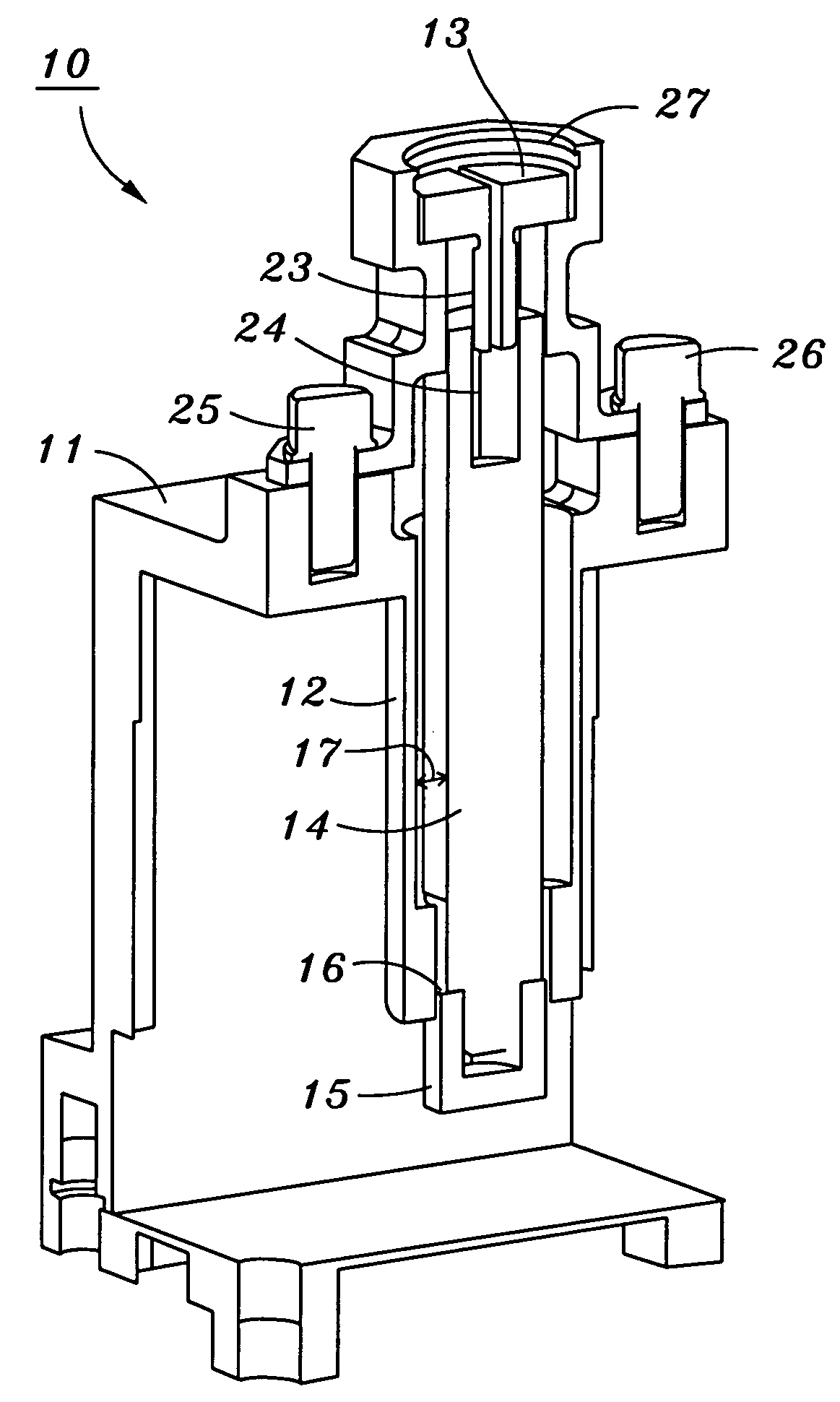
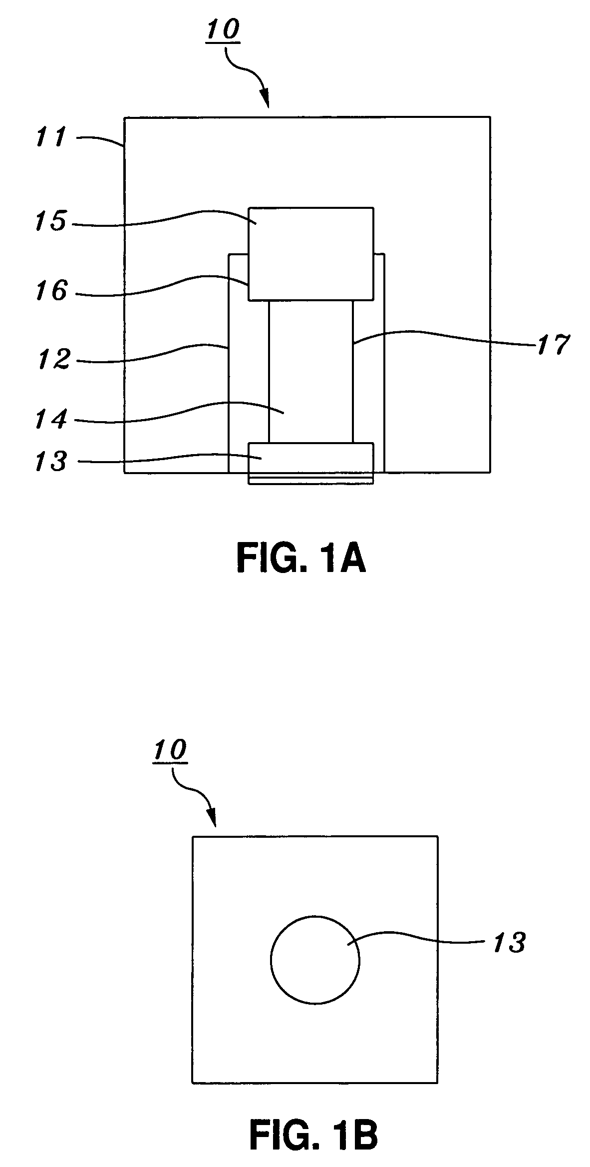
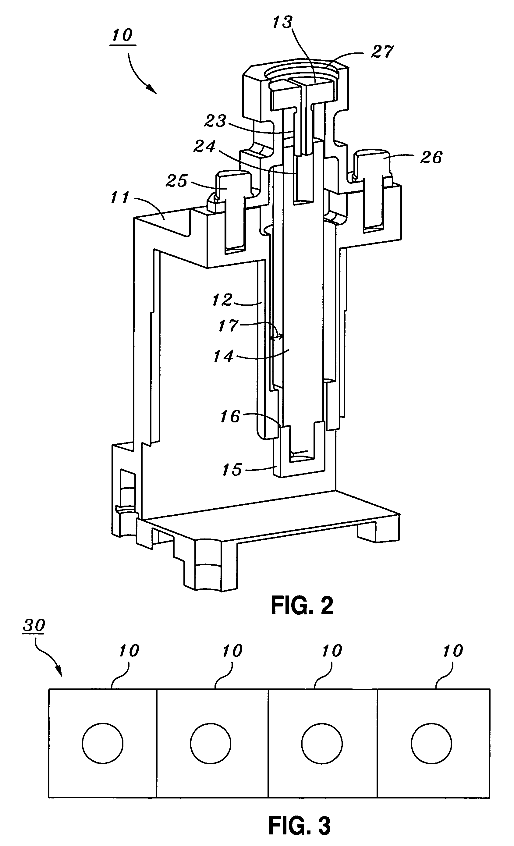
[0022]Turning to the drawings, FIG. 1A shows a side view of a tunable RF cavity resonator according to the present invention. As seen in FIG. 1A, tunable RF cavity resonator 10 is shown which is comprised of several components. Specifically, tunable RF cavity resonator 10 includes cavity body 11, fixed tuning post 12, dielectric rod 14, tuning element 15 and tuning screw 13. Cavity body 11 is preferably either a rectangular shape, such as a square, or a cylindrical shape, and has a cavity area disposed inside. Fixed tuning post 12 is disposed inside the cavity area of cav...


PUM


Abstract

A tunable RF cavity resonator having reduced generation of passive inter-modulation, the tunable RF cavity resonator including a cavity body, a fixed tuning post at a first end of the cavity body, a dielectric rod in the fixed tuning post interior space with a first spatial gap between the dielectric rod outer surface and the fixed tuning post inner wall, a tuning screw connected to a first end of the dielectric rod, and a tuning element disposed on a second end of the dielectric rod so that the tuning element moves within the interior space of the fixed tuning post while maintaining a second spatial gap between the tuning element outer surface and the fixed tuning post inner wall. Accordingly, the tuning element forms a short section of very low RF impedance transmission line thereby preventing RF signal leakage through the interior space of the fixed tuning post.

Description

STATEMENT AS TO RIGHTS TO INVENTIONS MADE UNDER FEDERALLY SPONSORED RESEARCH OR DEVELOPMENT[0001]NOT APPLICABLE TO THIS INVENTION.BACKGROUND OF THE INVENTION[0002]1. Field of the Invention[0003]The present invention concerns a re-entrant radio frequency (RF) cavity resonator filter which achieves a low level of generated passive inter-modulation (PIM) by having a tuning element which does not have contact with the fixed tuning post of the re-entrant cavity resonator.[0004]2. Description of the Related Art[0005]Conventional RF cavity resonators are typically tunable so that the resonator may be used across a given range of operating frequencies. Such a conventional RF resonator typically consists of a cavity body, either cylindrical or rectangular, in which a fixed tuning (resonator) post resides inside of the cavity body by being connected at one end to a wall of the cavity body. The fixed tuning post of the typical resonator is generally a tubular, cylindrical shape with a far end ...

Claims


Application Information

Patent Timeline
IPC IPC(8): H01P7/10H01P1/20H01P7/04
CPCH01P7/06
Inventor PATEL, KANTI N.CLARK, R. MARK
Owner LOCKHEED MARTIN CORP
Learn More