Electrical junction box
a junction box and electric technology, applied in the direction of coupling device connection, coupling device details, emergency protective devices, etc., can solve the problems of poor assembly workability, failure of fuses to be mounted, and inability to easily determine whether or not the first bus bar is installed
- Summary
- Abstract
- Description
- Claims
- Application Information
AI Technical Summary
Benefits of technology
Problems solved by technology
Method used
Image
Examples
first embodiment
[0051]With reference to the drawings, the present invention will be described below.
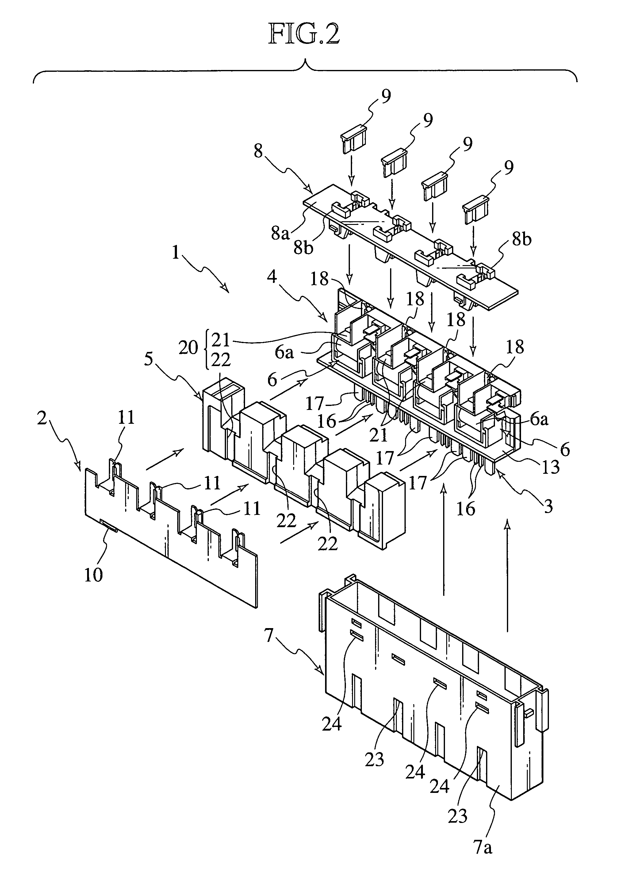
[0052]As shown in FIGS. 2 to 4, an electrical junction box 1 includes: a first bus bar 2; a bus bar attaching body 4 to which a second bus bar 3 is attached; an internal cover 5 which is attached to the bus bar attaching body 4 and covers relay parts 6; a case 7 which houses the first bus bar 2, the bus bar attaching body 4 and the internal cover 5; a fuse cavity 8 which is attached to an upper side of the case 7; and four fuses 9 which are mounted on fuse terminals 11 and 18 that are provided in the fuse cavity 8 in a protruding condition. Note that the arrow 30 in FIG. 4 shows a direction in which a water droplet W entering the case 7 through a fuse mounting part 8b is drained through a drainage channel in the electrical junction box 1.
[0053]The first bus bar 2 is manufactured by press-molding a rigid, conductive sheet metal having rigidity in a predetermined shape. A power terminal 10 is formed at...
second embodiment
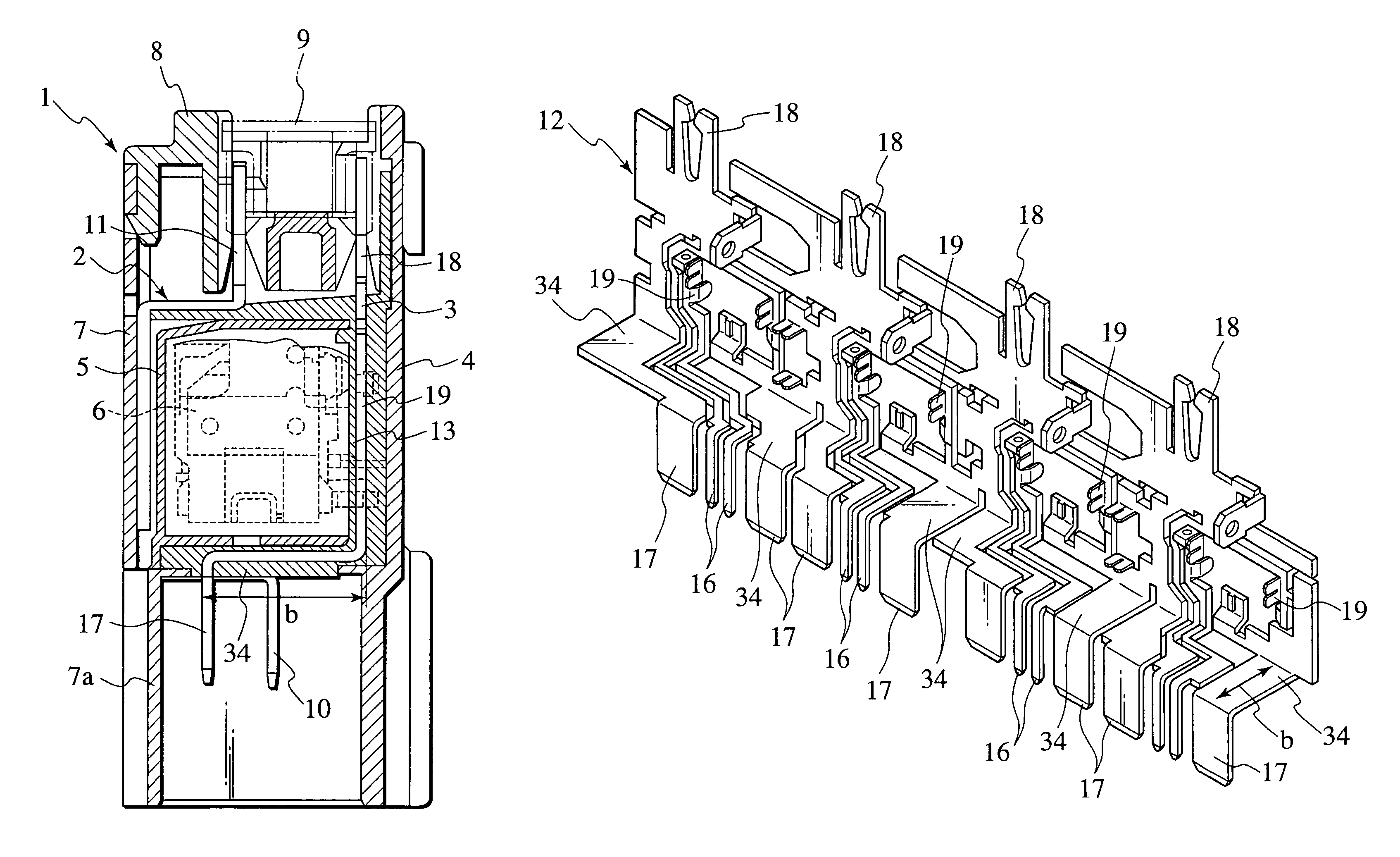
[0066]FIGS. 5 to 9 show how a bus bar positioning structure according to the present invention is applied to a bus bar housed in an electrical junction box.
[0067]As shown in FIGS. 5 and 6, an electrical junction box 1 includes: a first bus bar 2; a bus bar attaching body 4 to which a second bus bar 3 is attached; an internal cover 5 which is attached to the bus bar attaching body 4 and covers relay parts 6; a case 7 which houses the first bus bar 2, the bus bar attaching body 4 and the internal cover 5; a fuse cavity 8 which is attached to an upper side of the case 7; and four fuses 9 which are mounted on fuse terminals 11 and 18 that are arrayed in predetermined positions in a fuse cavity 8.
[0068]A first bus bar 2 is manufactured by press-molding a rigid, conductive sheet metal in a predetermined shape. A power terminal 10 is formed at a lower end of the first bus bar 2, and a fuse terminal 11 is formed in each of the four spots of an upper end thereof.
[0069]A bus bar attaching bod...
third embodiment
[0081]Next, with reference to FIGS. 10 and 11, an electrical junction box according to the present invention will be described.
[0082]As shown in FIG. 10, an electrical junction box 1 includes: a first bus bar 2; a bus bar attaching body 4 to which a second bus bar 3 is attached; an internal cover 5 which is attached to the bus bar attaching body 4 and covers relay parts 6; a case 7 which houses the first bus bar 2, the bus bar attaching body 4 and the internal cover 5; a fuse cavity 8 which is attached to an upper side of the case 7; and four fuses 9 which are mounted on fuse terminals provided in the fuse cavity 8 in a protruding condition.
[0083]The first bus bar 2 is manufactured by press-molding a rigid, conductive sheet metal in a predetermined shape. A power terminal 10 is formed at a lower end of the first bus bar 2, and a fuse terminal 11 is formed in each of the four spots of an upper end thereof.
[0084]A bus bar attaching body 4 is manufactured in the following manner. Speci...
PUM
 Abstract
Description
Claims
Application Information
 - R&D
- Intellectual Property
- Life Sciences
- Materials
- Tech Scout
- Unparalleled Data Quality
- Higher Quality Content
- 60% Fewer Hallucinations
Browse by: Latest US Patents, China's latest patents, Technical Efficacy Thesaurus, Application Domain, Technology Topic, Popular Technical Reports.
© 2025 PatSnap. All rights reserved.Legal|Privacy policy|Modern Slavery Act Transparency Statement|Sitemap|About US| Contact US: help@patsnap.com


