Resuscitators, parts and assemblies

a technology of resuscitation devices and parts, applied in the direction of respirators, trachea tubes, life-saving devices, etc., can solve the problem of low carbon dioxide level and indicate incorrect intubation

Inactive Publication Date: 2006-07-18
SMITHS GRP PLC
View PDF14 Cites 22 Cited by
  • Summary
  • Abstract
  • Description
  • Claims
  • Application Information

AI Technical Summary

Problems solved by technology

Hence, a low level of carbon dioxide is indicative of incorrect intubation.

Method used


Image

  • Resuscitators, parts and assemblies
  • Resuscitators, parts and assemblies
  • Resuscitators, parts and assemblies

Examples


Embodiment Construction

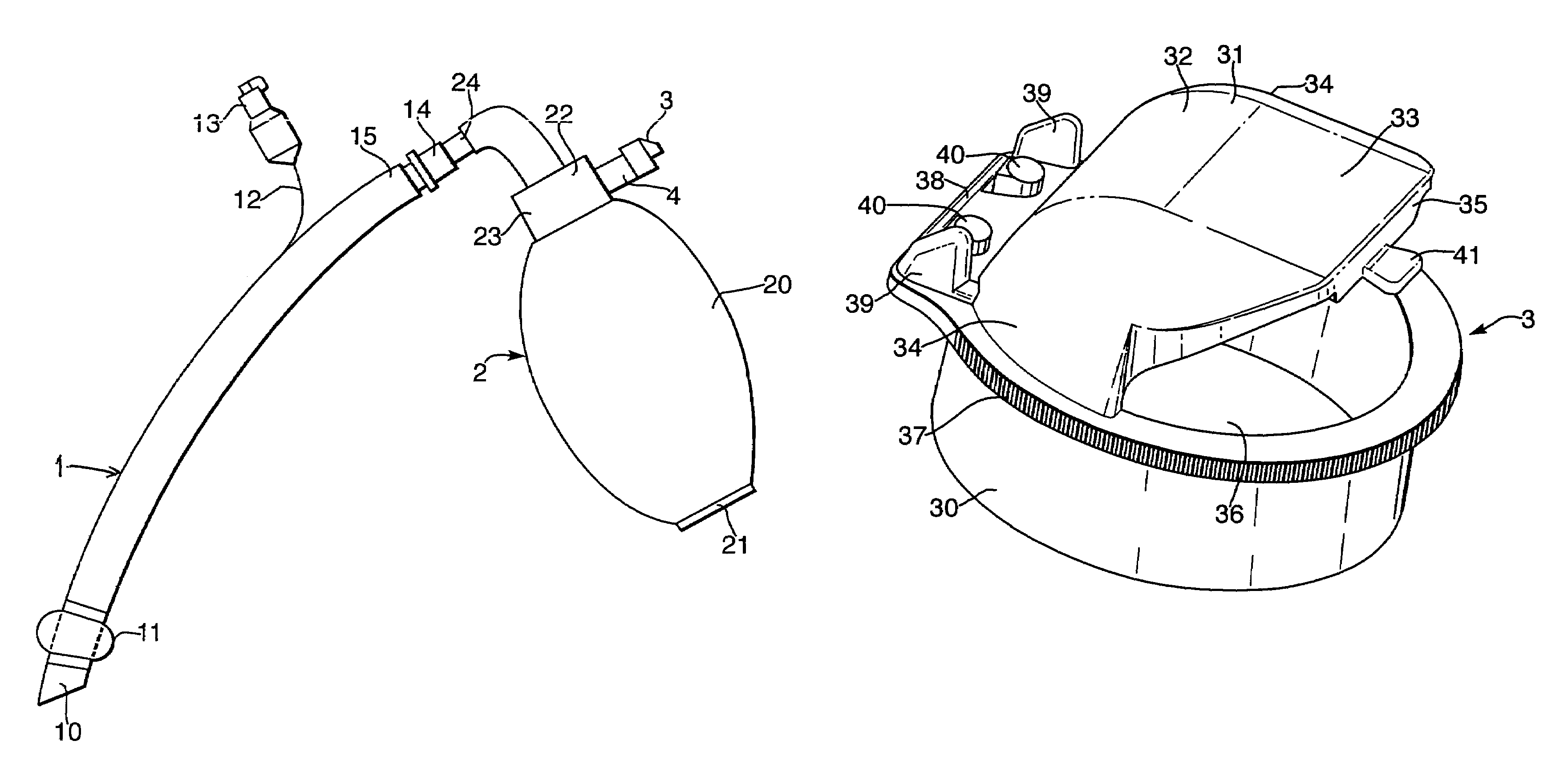
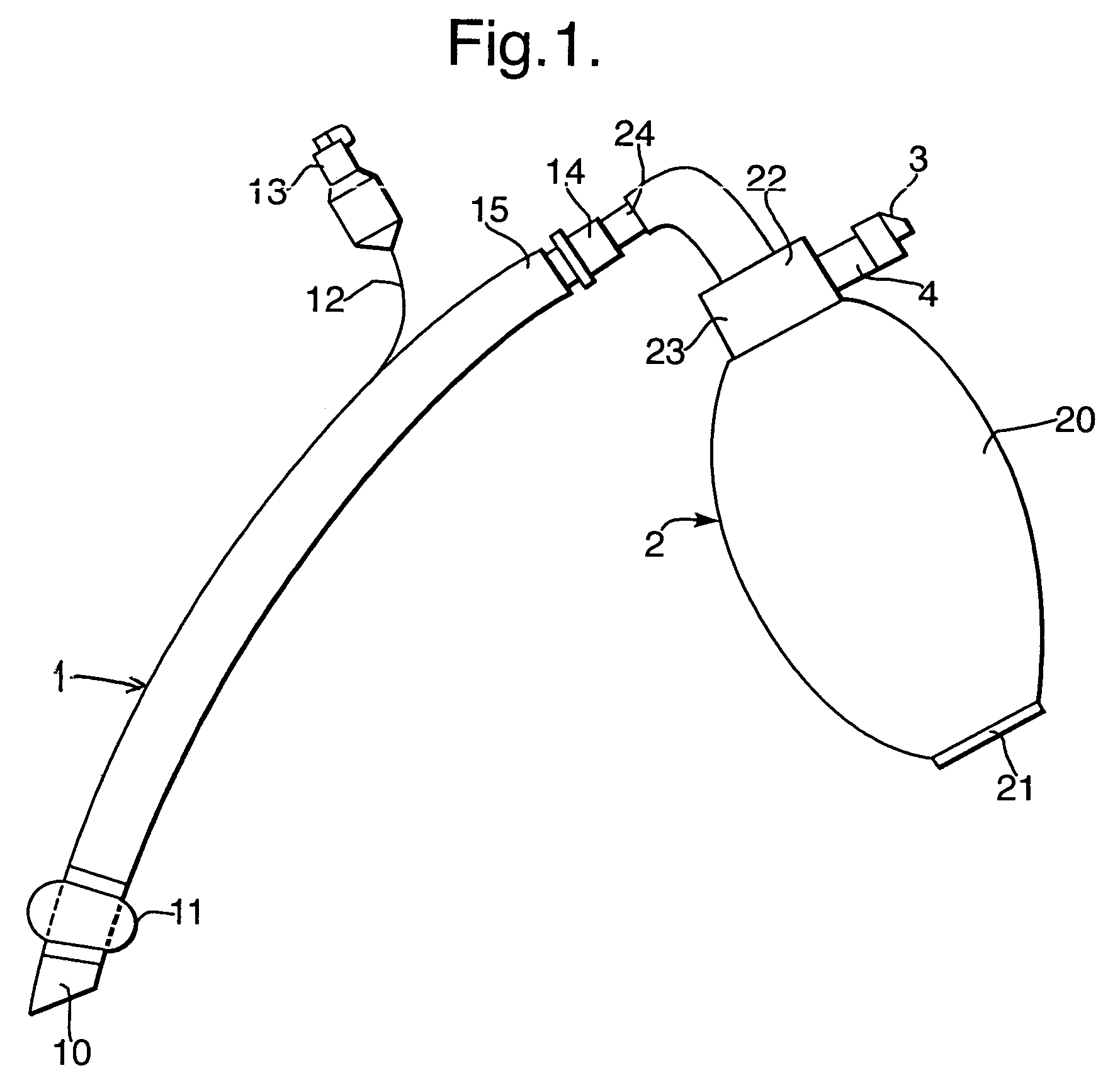
[0018]With reference first to FIG. 1, the assembly includes a conventional endotracheal tube 1, a squeeze-bag resuscitator 2 connected to the machine end of the tube and a flow diverter 3 connected on the exhaust outlet 4 of the resuscitator.

[0019]The patient end 10 of the endotracheal tube 1 is intended for placement in the trachea and has a cuff 11 towards its patient end that is inflatable via an inflation line 12 and connector 13, so that it seals with the trachea. A connector 14 is fitted in the machine end 15 of the tube 1.

[0020]The resuscitator 2 has a bulb-shape squeeze bag 20 of a resilient plastics material selected so that the bag can be squeezed by hand and recovers its original shape when released. At its lower end the resuscitator 2 has a one-way inlet valve 21 that allows air into the bag 20 when this is recovering its original shape but prevents flow of air out of the bag through the valve when the bag is squeezed. At its upper end the resuscitator 2 has a valve asse...


PUM


Abstract

A squeeze bag resuscitator has a flow diverter push fitted onto its exhaust outlet in any desired orientation. The diverter has a color change carbon dioxide indicator strip fixed to the inside surface of a transparent deflector plate. The indicator is protected from light externally by an opaque elastomeric strip attached by engaging surface formations to the outside of the plate. The indicator is also protected on the interior of the plate by an opaque strip, which projects from the diverter so that it can be removed by pulling on the free end.

Description

BACKGROUND OF THE INVENTION[0001]This invention relates to resuscitators, parts and assemblies.[0002]Resuscitators are used to ventilate a patient who is not breathing voluntarily. One type of resuscitator has a resilient squeeze bag that is squeezed by hand to administer air to a patient via a face mask, an endotracheal tube, laryngeal mask or the like. The resuscitator has a valve arrangement that directs air to a patient outlet coupling when the bag is squeezed and allows exhaled gas from the patient to flow directly to an exhaust outlet. The valve arrangement also allows air back in to refill the bag when it is released after having been squeezed. Where the resuscitator is used with an endotracheal tube it is important that checks are made to ensure that the tube is correctly placed, that is, to ensure it is in the trachea and not in the oesophagus. One way in which this can be done is by means of a carbon dioxide indicator since carbon dioxide is produced as a result of respira...

Claims


Application Information

Patent Timeline
Patent Type & Authority Patents(United States)
IPC IPC(8): A62B7/00A62B9/00A61M16/00A61M16/04A61M16/10A61M16/20
CPCA61M16/10A61M16/208A61M16/0084A61M2205/583A61M2230/432A61M2016/0413
Inventor PAGAN, ERIC
Owner SMITHS GRP PLC
Why Eureka
Try Eureka