Method and apparatus to reduce the width of a slot or opening in a pipe, tube or other object

a technology of slot or opening and pipe, which is applied in the direction of rolling mill control devices, manufacturing tools, metal rolling arrangements, etc., can solve the problems of inability to cut slots in tubulars in conventional manufacturing equipment, suffer from a number of inherent limitations, and the difficulty of slotting tubulars is not so much in their use but in their method of manufacturing, so as to reduce the width of the slot or opening, facilitate the alignment of seaming equipment, and reduce the effect of slot width

Active Publication Date: 2006-07-11
VARIPERM ENERGY SERVICES INC
View PDF37 Cites 7 Cited by
  • Summary
  • Abstract
  • Description
  • Claims
  • Application Information

AI Technical Summary

Benefits of technology

[0006]The invention therefore provides a method and an apparatus to reduce the width of a slot or opening in a pipe, tube or other object that facilitates in the alignment of seaming equipment with the slots or openings in the pipe or object, alleviates the need to completely treat the exterior surface of the product to reduce slot width, and that analyzes and tracks instances where treated slots or openings do not meet specification so that such slots or openings can be automatically re-treated.
[0008]In a further aspect the invention provides a method of reducing the width of a slot or opening in a pipe, the pipe having an outer surface and an inner surface with one or more slots or openings extending therebetween, the method comprising the steps of loading the pipe into a seaming machine, said seaming machine having one or more seaming heads, said one or more seaming heads and the pipe movable relative to one another, each of said one or more seaming heads including one or more seaming rollers movable from a position where they contact the surface of said pipe to a position where they are free from contract with the surface of said pipe; using said one or more seaming rollers to treat the exterior surface of said pipe adjacent to said one or more slots through the application of a compressive force to the exterior surface of said pipe to thereby reduce the width of said slots; following said treatment of the exterior surface of said pipe with said one or more seaming rollers, determining the width of said one or more slots in said pipe and the position of said one or more slots relative to the surface of said pipe; generating a signal corresponding to the determined width and relative position of said one or more slots following said treatment of the exterior surface of the pipe and directing said signal to a controller, said controller operatively connected to said one or more seaming rollers and controlling the position of said one or more seaming rollers relative to the surface of the pipe; with said controller comparing the determined width of said one or more slots to a pre-determined value and identifying slots having a width greater than said pre-determined value; and, causing said controller to move one or more of said seaming rollers into contact with the exterior surface of said pipe adjacent to said one or more slots having determined widths greater than said pre-determined value to selectively and compressively treat the exterior surface of the pipe at locations adjacent to said slots having determined widths greater than said pre-determined value and to thereby selectively further reduce the width of said slots.
[0009]The invention also concerns an apparatus for reducing the width of a slot or opening in a pipe, the pipe having an outer surface and an inner surface with one or more slots or openings extending therebetween, the apparatus comprising one or more compression tools independently movable from a position where they are free from contact with the surface of said pipe to a position where they contact the pipe's exterior surface and apply a compressive force thereto, when compressed against the exterior surface of said pipe adjacent to one or more of said slots said one or more compression tools reducing the width of said one or more slots; at least one slot measurement device, when activated said slot measurement device determining both the width and the relative position of one or more of said slots following the reduction of the width of said one or more slots, said slot measurement device further generating a signal corresponding to the determined width and relative position of said one or more slots; a controller, said controller receiving said generated signal and comparing the determined width of said one or more slots with a pre-determined value to identify slots having widths greater than said pre-determined value; and, means to cause one or more of said compression tools to be moved to selectively contact the surface of said pipe adjacent to slots having determined widths greater than said pre-determined value to selectively and further reduce the width of said slots.
[0010]In addition, the invention also concerns a method to reduce the width of a slot or opening in a pipe, the pipe having an outer surface and an inner surface with one or more slots or openings extending between its outer and inner surfaces, the method comprising the steps of determining the position of said one or more slots relative to the surface of the pipe; determining the width of said one or more slots in said pipe; generating a signal corresponding to the determined width and relative position of said one or more slots and directing said signal to a controller; with said controller comparing the determined width of said one or more slots with a pre-determined value and identifying slots having widths greater than said pre-determined value; and, with said controller causing the exterior surface of said pipe adjacent to said one or more slots having determined widths greater than said pre-determined value to be treated through causing one or more compression tools to be moved to selectively contact the exterior surface of said pipe adjacent to said identified slots so as to selectively reduce the width of said slots.

Problems solved by technology

The difficulty encountered with slotted tubulars is not so much in their use but in their method of manufacturing.
Unfortunately, conventional manufacturing equipment is rarely capable of cutting slots in tubulars effectively having a width less than 0.015 inches.
Although the seaming methods that have been used by others have been generally successful, they also suffer from a number of inherent limitations.
First, the alignment of seaming equipment with the slots or openings has proven to be difficult and often requires considerable operator effort and skill.
While doing so may to a large degree alleviate alignment issues, it also significantly slows down the seaming process since the entire exterior surface of the product must be treated.
Currently available methods also provide no mechanism for continuously checking the degree to which the width of the slots or openings have been reduced, or to accurately track instances where treated slots or openings do not meet specifications.

Method used


Image

  • Method and apparatus to reduce the width of a slot or opening in a pipe, tube or other object
  • Method and apparatus to reduce the width of a slot or opening in a pipe, tube or other object
  • Method and apparatus to reduce the width of a slot or opening in a pipe, tube or other object

Examples


Embodiment Construction

[0022]The present invention may be embodied in a number of different forms. However, the specification and drawings that follow describe and disclose only some of the specific forms of the invention and are not intended to limit the scope of the invention as defined in the claims that follow.

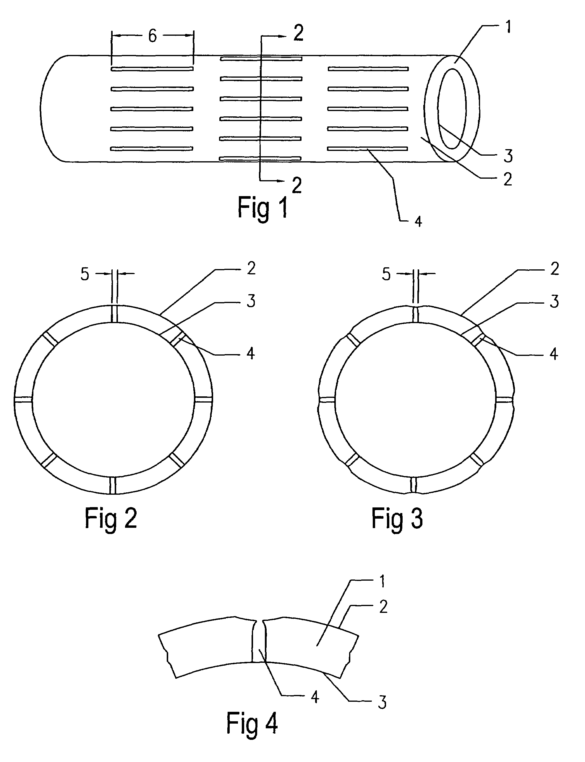
[0023]It should be noted that the invention described herein may be practiced in association with a wide variety of different types, shapes and sizes of objects or products having slots, holes or openings within their outer surfaces. For illustration purposes the specific embodiments of the invention that are described below concern the use of the invention in connection with a slotted pipe or tubular member. Accordingly, pursuant to one of the preferred embodiments of the invention there is provided a pipe, tube, or tubular element 1 having an outer surface 2 and an inner surface 3 (see FIG. 1). Spaced about the outer surface of tubular member 1 is a series of slots or openings 4, having a widt...


PUM

PropertyMeasurementUnit
widthaaaaaaaaaa
diametersaaaaaaaaaa
widthaaaaaaaaaa

Abstract

A method to reduce the width of slots or openings in a pipe. The method involve determining the position of the slots relative to the surface of the pipe and determining the width of the slots. A signal is generated corresponding to the determined width and relative position of the slots and the signal is directed to a controller. The controller compares the determined width of the slots with a pre-determined value and identifies slots having widths greater than the pre-determined value. The exterior surface of the pipe adjacent to the slots having determined widths greater than the pre-determined value is treated through causing one or more compression tools to be moved to selectively contact the exterior surface of the pipe adjacent to the identified slots so as to selectively reduce the width of the slots.

Description

FIELD OF THE INVENTION[0001]This invention relates to a method and to an apparatus to reduce the width of a slot or opening in a pipe, tube or other object, and in one aspect to a method and an apparatus to reduce the width of slots in tubular liners for well bore holes.BACKGROUND OF THE INVENTION[0002]Slotted metal pipes, or tubulars as they are often known, have been used for a considerable length of time in oil, gas and water wells as a means to limit the amount of sand or debris allowed to enter the tubular as oil, gas or water is drawn in from surrounding underground formations. The slotted tubulars effectively act as a liner and screening mechanism to permit the desired fluid to be drawn into the tubular for extraction while excluding sand, rock and other particles. Tubular liners must have slots that are sufficiently small in width to prevent particulate matter from entering the pipe, while maintaining sufficient structural integrity to withstand pressures to which they may b...

Claims


Application Information

Patent Timeline
Patent Type & Authority Patents(United States)
IPC IPC(8): B21D3/02
CPCB21D22/14B21D31/02
Inventor HRUSCHAK, LAWRENCE ALEXANDERMCLEAN, TERRY JAMESARISS, RICHARD TODD
Owner VARIPERM ENERGY SERVICES INC
Why Eureka
Try Eureka