
Clip-on wire identification markers

a technology of identification markers and clip-on wires, applied in the field of identification markers, can solve the problems of difficult application and difficult reading of text, and achieve the effect of easy rotation and maximum legibility

Inactive Publication Date: 2006-07-11
BRADY WORLDWIDE INC
View PDF19 Cites 79 Cited by
  • Summary
  • Abstract
  • Description
  • Claims
  • Application Information

AI Technical Summary

Benefits of technology

This patent describes a special marker that can be attached to wires and cables for easy identification. The marker has a flat surface for printing or attaching with adhesive and contains two holes that can be clipped onto the wire. The marker can be rotated for easy reading and is printable on both sides. The technical effects of this invention are that it solves the problems of easy attachment, readability of extended text, holding close to the wire, and economic use of materials for various terminated and non-terminated elongated objects.

Problems solved by technology

Although these markers often offer good holding or affixation power, they can be difficult to apply.
If it contains extended text, then this text can be difficult to read because the marker cannot be easily rotated, if rotated at all, about the wire.
While psa, sleeve and tag markers can withstand these environments when designed for them, they often do so by sacrificing ease of installation or low price, or requiring a compact, close to the wire configuration.

Method used


Image

  • Clip-on wire identification markers
  • Clip-on wire identification markers
  • Clip-on wire identification markers

Examples


Embodiment Construction

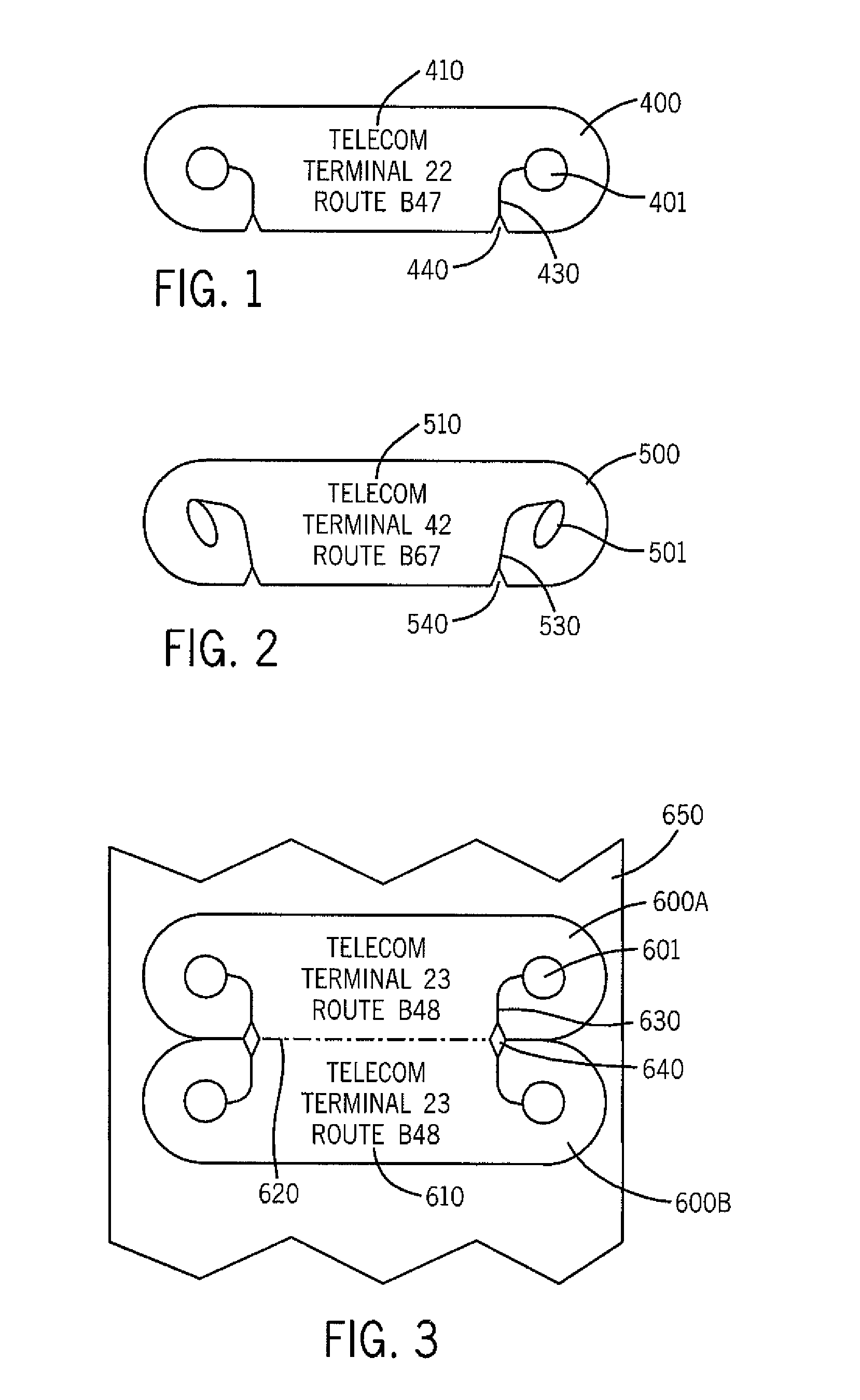
[0019]FIG. 1 illustrates a clip-on marker 400. The marker has a generally elongated oval configuration with holes or apertures 401 near each curved end of the oval. Slots or cuts 430 extend from the interior (relative to the marker) of holes 401 to one straight side or edge of the marker. Optionally, the slots or cuts 430 extend from holes 401 to notches 440. The notches are sized, shaped and cut to easily guide a wire or other elongated object into and through the slots and into the holes. The top surface of the marker bears indicia 410.

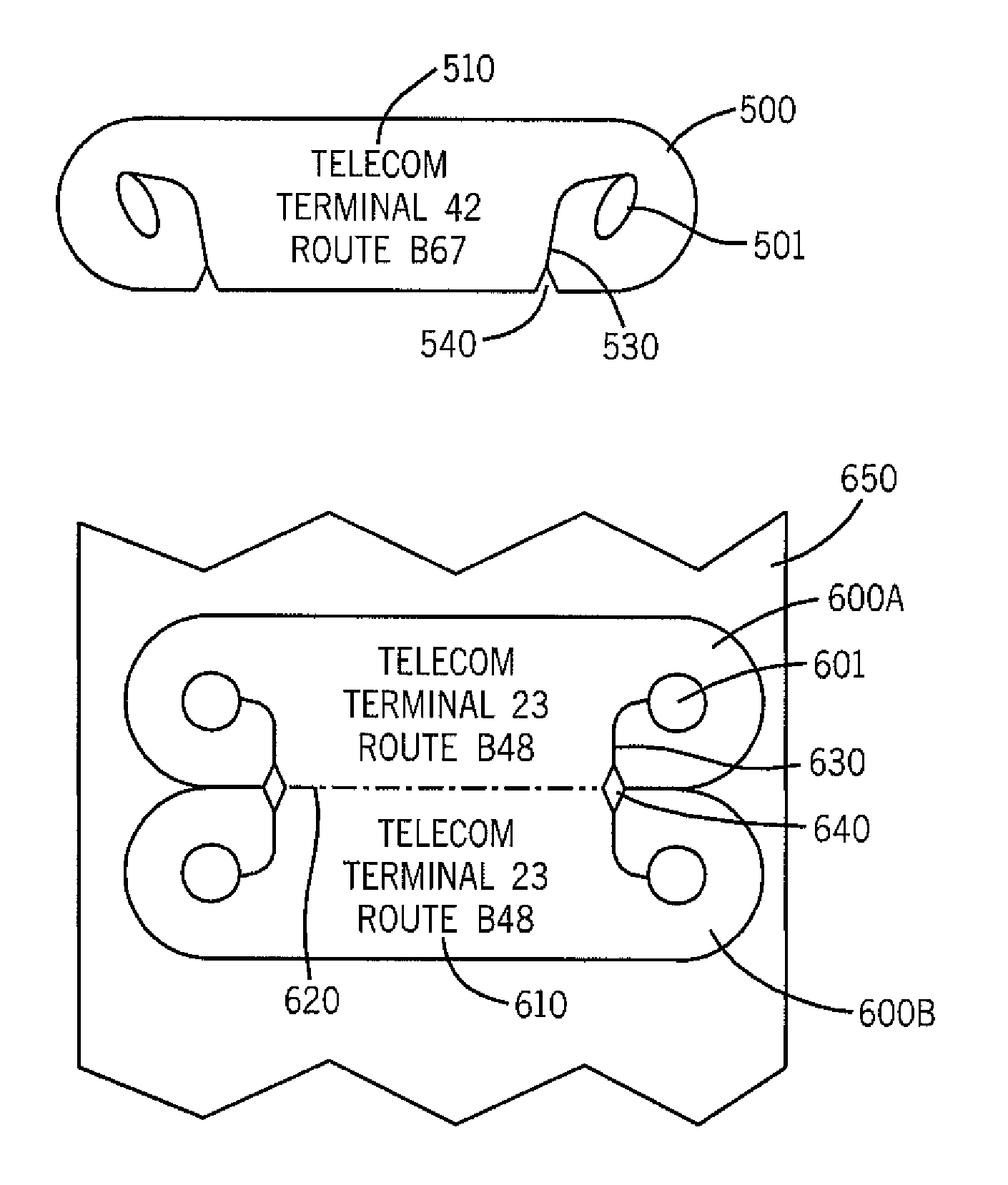
[0020]FIG. 2 illustrates clip-on design 500 which is alike in all ways to design 400 except for the size and shape of the holes and slots. Apertures 501 have an oval configuration, and slots 530 are more extended than slots 430 and terminate at notches 540. In fact, the holes or apertures of the markers of this invention can be shaped and sized as desired to optimize the ease of application and retention power of markers. Marker 500 bears indicia 51...


PUM


Abstract

An identification marker or tag for wires and other elongated objects is described. In one embodiment, the marker has a generally elongated shape, e.g., an elongated oval, and comprises a surface for bearing indicia and two holes, one hole located near each end of the marker. Each hole is connected to an edge of the marker by a slot or cut that is adapted for ease of clipping the marker onto a wire. The marker is dimensioned in length and width to display text in the font size desired to maximize legibility.

Description

FIELD OF THE INVENTION[0001]This invention relates to identification markers. In one aspect, the invention relates to identification markers adapted for attachment to a wire or other elongated object while in another aspect, the invention relates to such markers adapted for clip-on attachment. In still another aspect, the invention relates to a method of producing the markers and the markers in a ribbon assembly for easy distribution, storage, printing and use.BACKGROUND OF THE INVENTION[0002]Many regulations, common practice and just plain common sense require the clear marking of various elongated objects, e.g., electrical wires and cables, tubes, pipes, and the like. These markers require permanency and legibility, and they require ease of application and permanency of affixation for both new and existing installations.[0003]The most common identification methods for wires and cables are pressure sensitive adhesive (psa) markers that are printed and either wrapped around the obje...

Claims


Application Information

Patent Timeline
Patent Type & Authority Patents(United States)
IPC IPC(8): G09F3/00G08B13/24G09F3/02G09F3/04
CPCG09F3/0295G09F3/04Y10T24/3924
Inventor SAVAGIAN, MICHAEL D.MESS, STEVEN H.
Owner BRADY WORLDWIDE INC
Learn More