
View dependent tiled textures

a tiled texture and dependent technology, applied in the field of tiled texture mapping, can solve the problems of lack of depth characteristics, lack of realism, and poor depth characteristics of the traditional tiled texture of for example a brick wall, and achieve the effects of improving detail and realism in an image, facilitating image processing, and high resolution

Inactive Publication Date: 2006-07-04
MICROSOFT TECH LICENSING LLC
View PDF17 Cites 16 Cited by
  • Summary
  • Abstract
  • Description
  • Claims
  • Application Information

AI Technical Summary

Benefits of technology

[0002]In computer graphics texture mapping refers to adding texture, color, shading, illumination, transparency, as well as other image attributes, to the surface of an image geometry to increase the detail and realism in an image. (In this context, image geometry refers to an image surface to be rendered on a video display and is not a limited to image objects representing solid articles.) Commonly, texture mapping utilizes a texture tile (or tiled texture) that includes the image attributes of the texture and is typically smaller than the image geometry to which the texture mapping is applied. As a result, texture mapping often entails applying an array of many copies of the texture tile to the image geometry (i.e., tiling) to cover it with the image or surface texture. Texture mapping simplifies image processing by allowing image modeling calculations to be based on image geometries alone without also having to model relatively high resolution and complex surface details.

Problems solved by technology

Conventional tiled textures and texture mapping suffers from relatively poor depth characteristics and therefore lack realism.
In conventional texture mapping for computer graphics, however, the depth characteristics of the typical tiled texture of for example a brick wall are lacking.
Whenever tiles formed by perspective or orthographic projections at different viewing angles are positioned together, image artifacts arising from inconsistencies in their views undermine the goal of improved depth characteristics.
In particular, tiles with perspective projections undergo second perspective projections after the tiles are applied to an image geometry, which results in undesirable image artifacts.

Method used


Image

  • View dependent tiled textures
  • View dependent tiled textures
  • View dependent tiled textures

Examples


Embodiment Construction

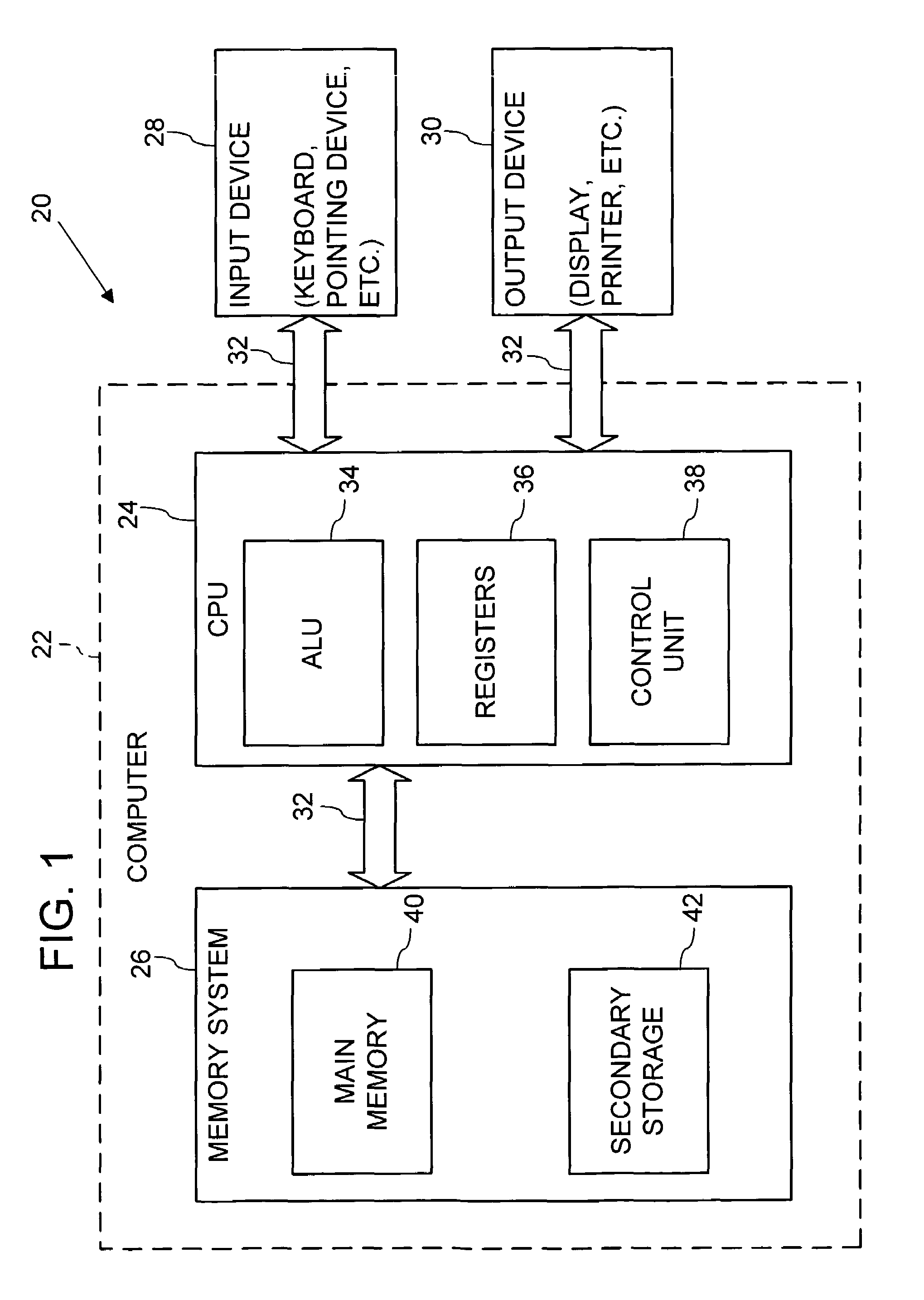
[0023]FIG. 1 illustrates an operating environment for an embodiment of the present invention as a computer system 20 with a computer 22 that comprises at least one high speed processing unit (CPU) 24 in conjunction with a memory system 26, an input device 28, and an output device 30. These elements are interconnected by at least one bus structure 32.

[0024]The illustrated CPU 24 is of familiar design and includes an ALU 34 for performing computations, a collection of registers 36 for temporary storage of data and instructions, and a control unit 38 for controlling operation of the system 20. The CPU 24 may be a processor having any of a variety of architectures including Alpha from Digital, MIPS from MIPS Technology, NEC, IDT, Siemens, and others, x86 from Intel and others, including Cyrix, AMD, and Nexgen, and the PowerPC from IBM and Motorola.

[0025]The memory system 26 generally includes high-speed main memory 40 in the form of a medium such as random access memory (RAM) and read o...


PUM


Abstract

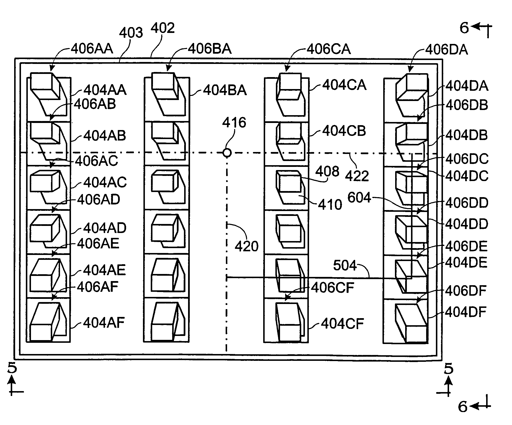
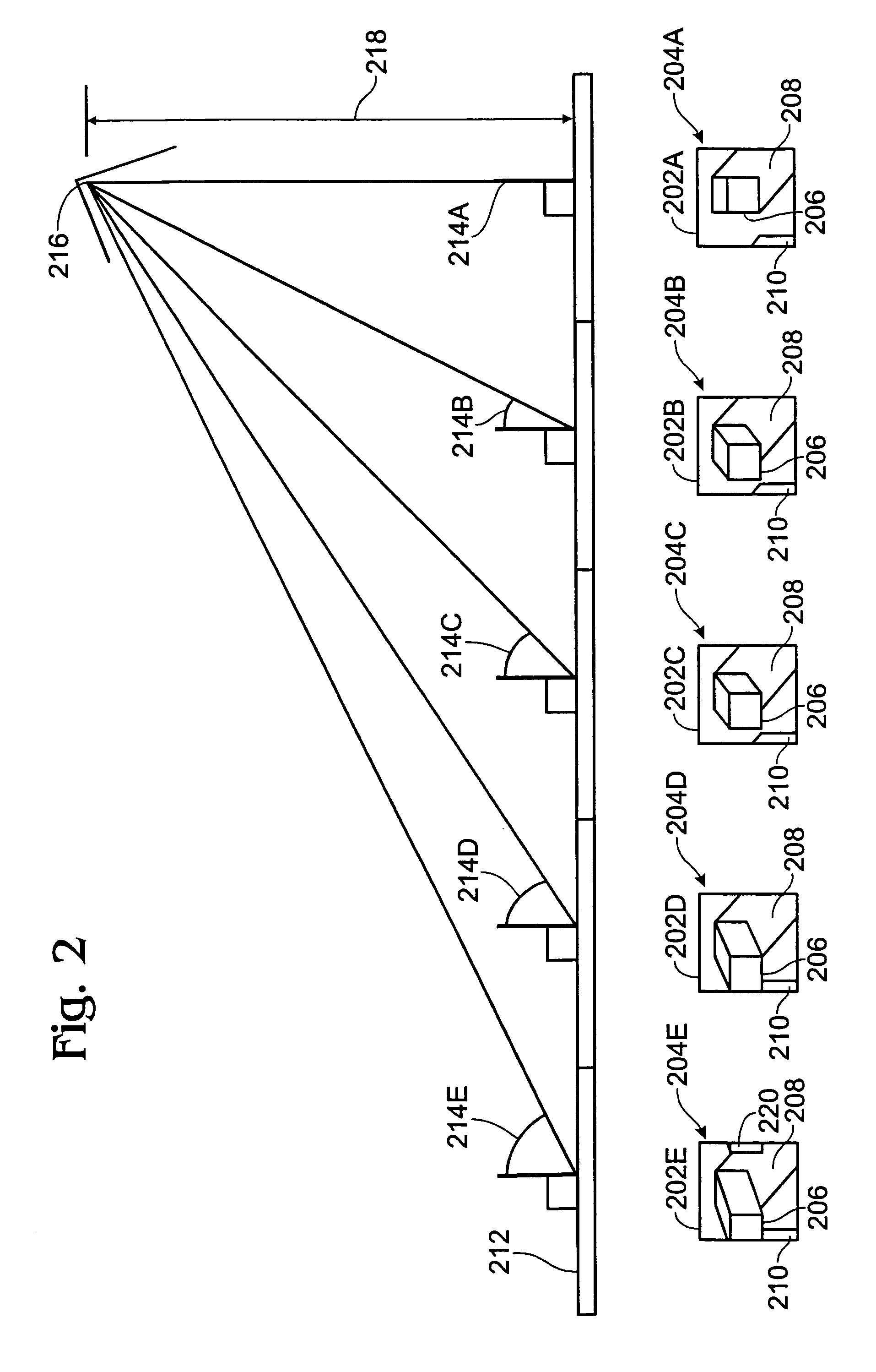
An array of view-dependent sprited tiles provide different views of an image texture (e.g., structure, color, shading, illumination, transparency, as well as other image attributes). The different views of the image texture correspond to different viewing angles at which a user would see the tiles when they are applied to an image geometry. In one implementation, the view dependent sprited tiles are two-dimensional projections of three-dimensional structures. The projections maintain the dimensions (including shape) of the front surfaces of three-dimensional structures at different viewing angles. A projection that meets these characteristics is the oblique parallel projection.

Description

FIELD OF THE INVENTION[0001]The present invention relates to tiled texture mappings in computer graphics displays and, in particular, to tiles that that are rendered according to different user viewing angles.BACKGROUND AND SUMMARY OF THE INVENTION[0002]In computer graphics texture mapping refers to adding texture, color, shading, illumination, transparency, as well as other image attributes, to the surface of an image geometry to increase the detail and realism in an image. (In this context, image geometry refers to an image surface to be rendered on a video display and is not a limited to image objects representing solid articles.) Commonly, texture mapping utilizes a texture tile (or tiled texture) that includes the image attributes of the texture and is typically smaller than the image geometry to which the texture mapping is applied. As a result, texture mapping often entails applying an array of many copies of the texture tile to the image geometry (i.e., tiling) to cover it w...

Claims


Application Information

Patent Timeline
Patent Type & Authority Patents(United States)
IPC IPC(8): G09G5/02
CPCG06T15/04
Inventor DRUCKER, STEVEN M.MAHONEY, JAMES M.
Owner MICROSOFT TECH LICENSING LLC
Learn More