Motor control apparatus, and washing machine and drying machine using the same
a technology of motor control and control apparatus, which is applied in the direction of electronic commutators, motor/generator/converter stoppers, dynamo-electric converter control, etc., can solve the problems of motor efficiency being out of the best point, the mounting position of the position sensor is expensive, and the effect of reducing the size and cos
- Summary
- Abstract
- Description
- Claims
- Application Information
AI Technical Summary
Benefits of technology
Problems solved by technology
Method used
Image
Examples
first embodiment
(Configuration)
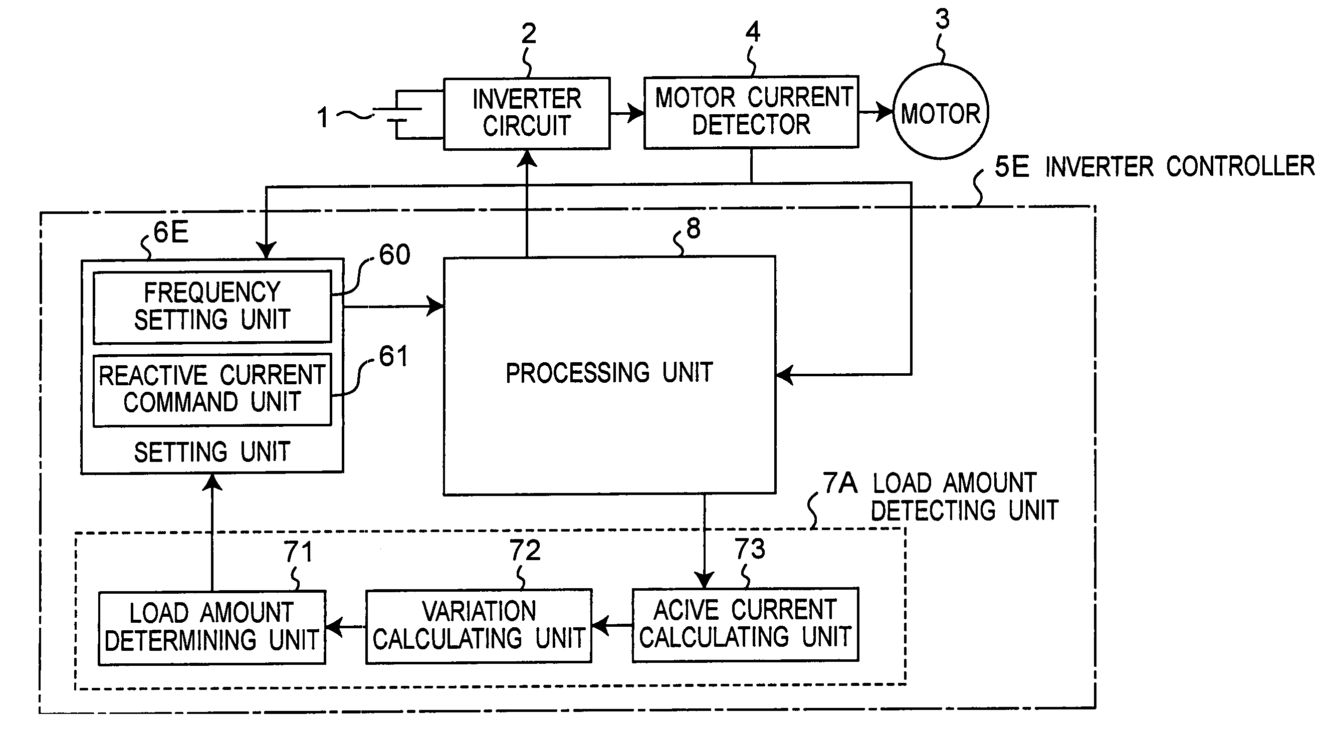
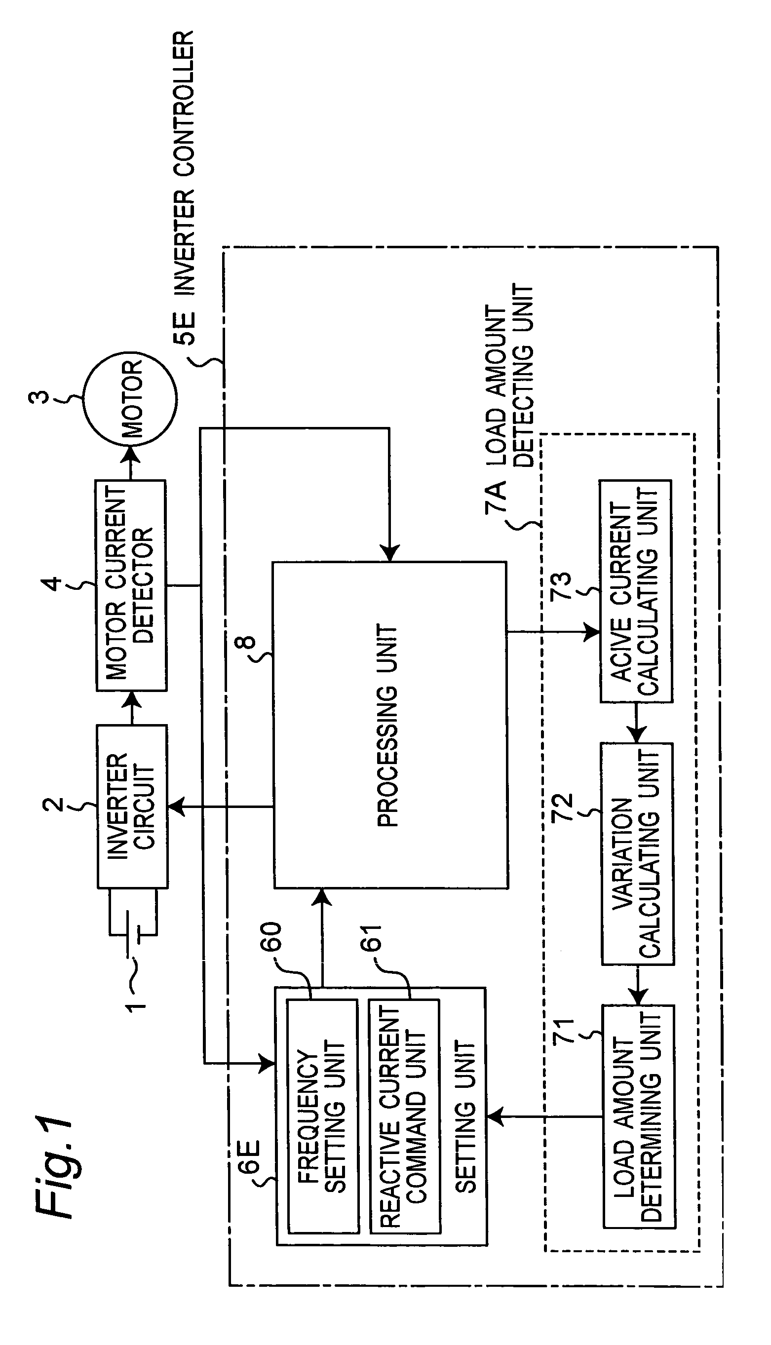
[0053]The first preferred embodiment of a motor control apparatus of the invention is described. FIG. 1 is a block diagram of the motor control apparatus in the first embodiment. The motor control apparatus includes an inverter circuit 2 for converting a DC (direct-current) voltage from a DC power source 1 into an AC (alternating-current) voltage for driving a motor 3, a motor current detector 4 for detecting the current flowing in the motor 3, and an inverter controller 5E for controlling the inverter circuit 2.
[0054]The motor 3 may be, for example, a synchronous brushless motor and includes no position sensor for detecting the rotor position.
[0055]The inverter circuit 2 has six switching elements (for example, thyristor, GTO, transistor, etc.) for composing three phases of arms, and diodes connected in parallel to the switching elements. The inverter circuit 2 takes in DC power from the DC power source 1, and converts the power into AC power in response to the contr...
second embodiment
[0085]FIG. 12A is a block diagram of the motor control apparatus in the second embodiment of the invention. It should be noted that the load amount detecting unit 7 is any one of the load amount detecting units 7A to 7D described above (it is the same in the following embodiments).
[0086]FIG. 12B specifically shows the structure of the setting unit 6A. The setting unit 6A includes a frequency setting unit 60, a reactive current command unit 61, a V / f converter 81, adders 82, 83, a waveform generating unit 84, a reactive current calculating unit 85, and an error voltage output unit 86. The reactive current command unit 61 outputs a command value Ir* (hereinafter referred to as “reactive current command value”) of reactive current component value Ir of motor current Is.
[0087]The frequency setting unit 60 sets command value of frequency of AC power output from the inverter circuit 2 to determine rotating speed of the motor 3. The frequency command value set is sent into the waveform gen...
third embodiment
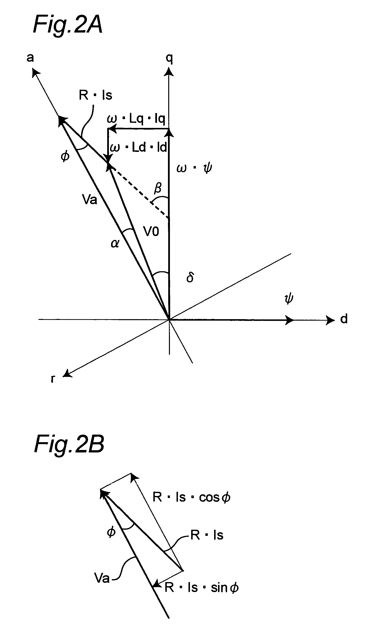
[0092]FIG. 14 is a block diagram of the motor control apparatus in the third embodiment of the invention. In the figure, the motor control apparatus has a phase difference φ command unit 62 instead of the reactive current command unit 61 in the second embodiment. The other structure is the same as the second embodiment. The phase difference φ is the difference in phase between applied voltage command Va and motor current Is. The phase difference φ is determined in the following formula.
[0093]ϕ=tan-1(IrIa)(3)
[0094]FIG. 15 is a diagram showing the relation between phase difference φ command value and output torque when the motor rotating speed and applied voltage are constant. In FIG. 15, driving points a, b, c, d correspond to those shown in FIG. 3. It is known from this figure that the driving point can be set by using the phase difference φ command value.
[0095]That is, the phase difference φ command value is set so as to correspond to the amount of the output torque by the phase d...
PUM
 Abstract
Description
Claims
Application Information
 - R&D
- Intellectual Property
- Life Sciences
- Materials
- Tech Scout
- Unparalleled Data Quality
- Higher Quality Content
- 60% Fewer Hallucinations
Browse by: Latest US Patents, China's latest patents, Technical Efficacy Thesaurus, Application Domain, Technology Topic, Popular Technical Reports.
© 2025 PatSnap. All rights reserved.Legal|Privacy policy|Modern Slavery Act Transparency Statement|Sitemap|About US| Contact US: help@patsnap.com


