
Display pixel module for use in a configurable large-screen display application and display with such pixel modules

a pixel module and display technology, applied in the field of pixels, can solve the problems of cumbersome fixing methods of led modules to frames, large display requirements, and inability to adapt to the variety of applications, and achieve the effect of convenient installation

Inactive Publication Date: 2006-07-04
BARCO NV
View PDF13 Cites 69 Cited by
  • Summary
  • Abstract
  • Description
  • Claims
  • Application Information

AI Technical Summary

Benefits of technology

The invention provides a pixel module design that is easy to install and can be used in various shapes. The module has tapered walls that allow for easy assembly and mounting on a display surface. The module can be easily replaced from the front or rear of a large-scale display. The module is designed with interconnected parts that can be easily assembled and interconnected with other electronic components of the display or other pixel modules. The invention also includes a display comprising multiple pixel modules arranged on a mounting surface to form a 2D or 3D display.

Problems solved by technology

The market is now, however, demanding larger displays with the flexibility to customize display sizes and colors which are not possible with these older technologies.
However, standard metal brackets are restrictive, often yielding only orthogonal two-dimensional (2D) displays, and therefore do not lend themselves to the variety of applications in which the front face of the overall display is a simple or complex three-dimensional (3D) curved surface.
Technical challenges exist in forming a display system with the flexibility to form various 2D or 3D shapes and, furthermore, in providing control of such a system.
In addition, brackets and other similar support systems often employ cumbersome methods of fixing LED modules to the frame, such as mechanical fasteners.
Such methods do not allow for the easy removal and replacement of individual LED modules, thereby making maintenance difficult.
For example, in a current system, if a LED module becomes inoperative, replacement typically requires access to the rear of the display and involves removing screws, bolts, connectors and other mechanical fasteners, resulting in a process that is tedious and time consuming.

Method used


Image

  • Display pixel module for use in a configurable large-screen display application and display with such pixel modules
  • Display pixel module for use in a configurable large-screen display application and display with such pixel modules
  • Display pixel module for use in a configurable large-screen display application and display with such pixel modules

Examples


Embodiment Construction

[0025]The present invention is a pixel display module, in particular a LED display module, that implements a small array of LED pixels for use in a scaleable large-screen display application.

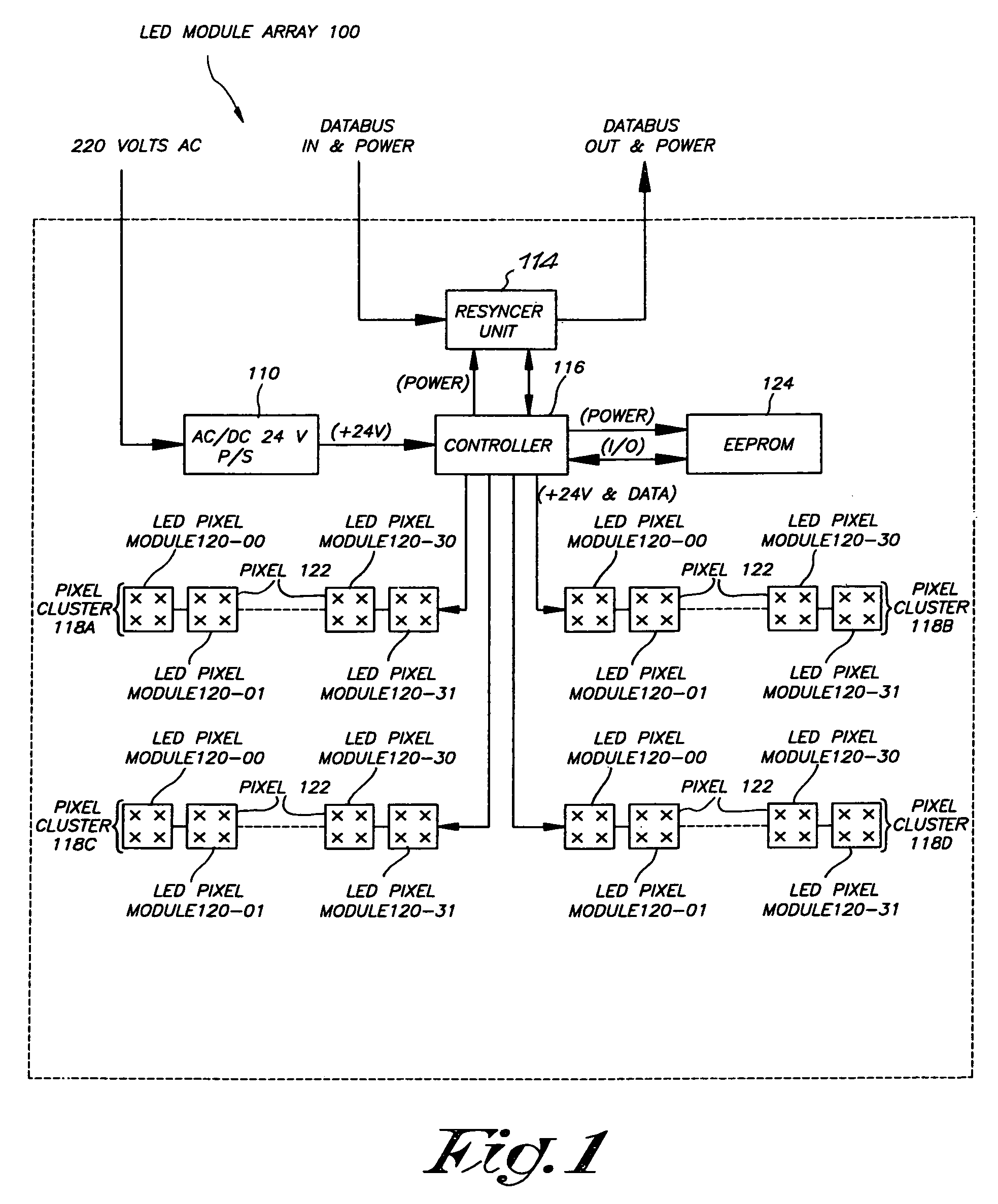
[0026]FIG. 1 is a functional block diagram of a pixel module array 100, in particular a LED module array, which is, for example, a portion of a larger LED display system (not shown) formed of a sequential string of similar LED module arrays 100. A detailed description of a LED display system is found in reference to another patent application of the same applicant.

[0027]While the specific embodiment of the module concept of the present invention is demonstrated by use of LED module array 100, any kind of addressable display technology may be used, be it phosphorescent, electroluminescent, organic / inorganic emissive, reflective or other known display technologies.

[0028]LED module array 100 includes an AC-to-DC (AC / DC) converter 110, a resynchronizer (resyncer) unit 114, and a controller 116 drivi...


PUM


Abstract

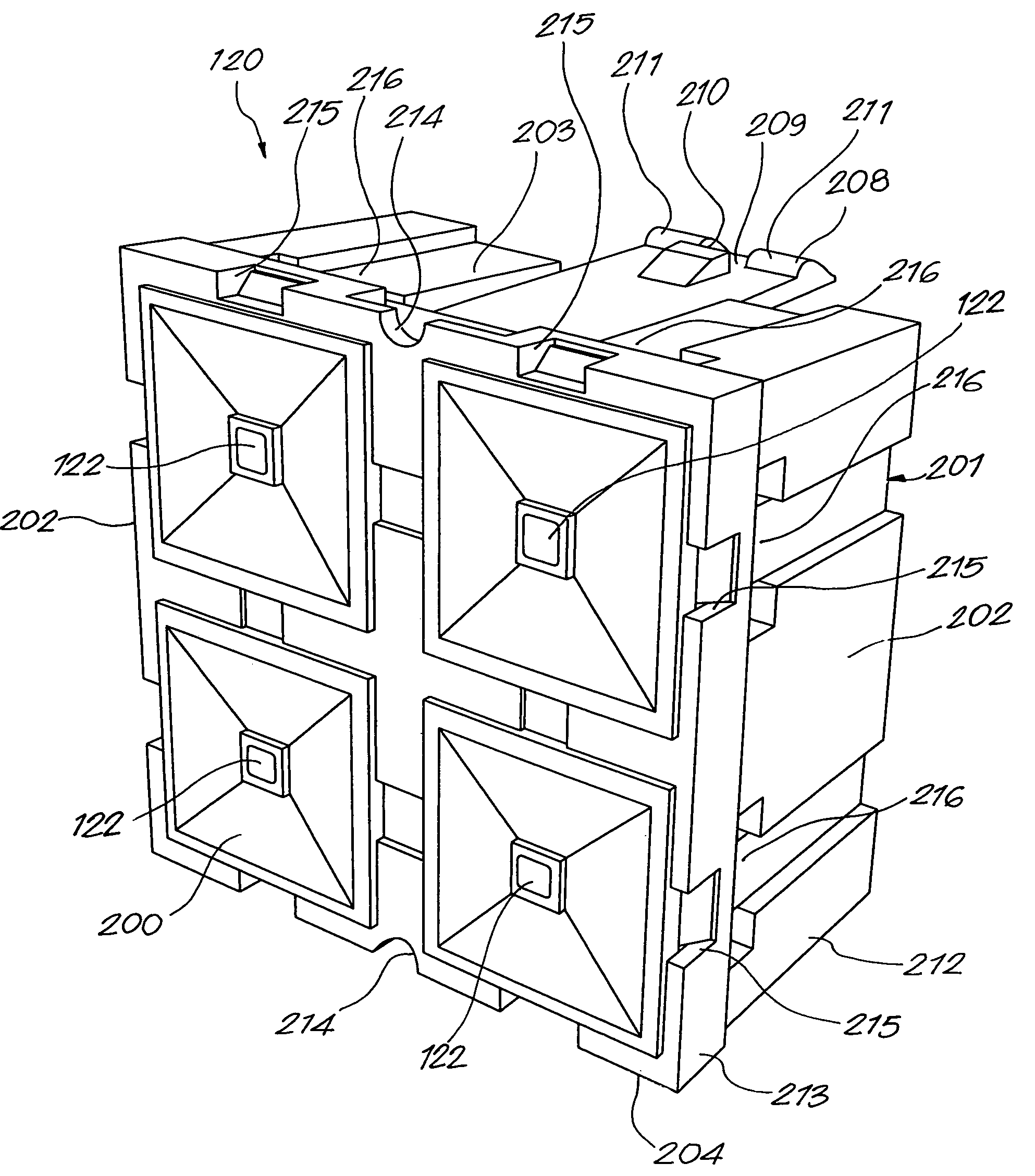
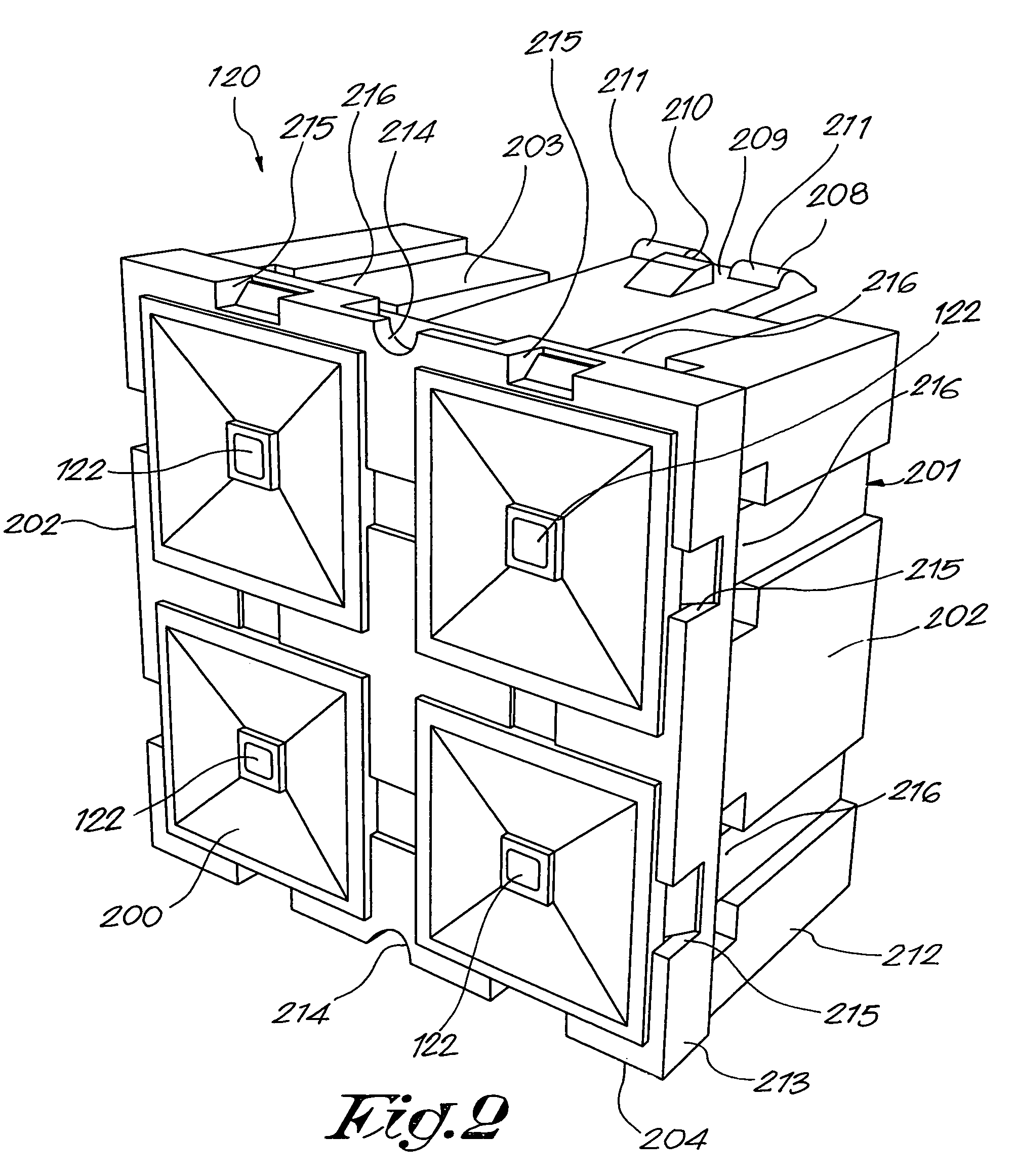
A display pixel module for use in a configurable large-screen display application, with an array of pixels (122) mounted at the front (200) of the module (120) and provided with input and output connectors (206–207), characterized in that at least some of the side walls (202) and of the upper and lower walls (203–204) are tapered inwardly, enclosing an angle (A) with the front (200) and in that it is provided with mounting means to fix the module on a mounting surface of a display.

Description

FIELD OF THE INVENTION[0001]The present invention relates to a pixel module for use in a configurable modular large-scale display. In particular, this invention relates to a scalable display element consisting of a pixel module, preferably a light-emitting diode (LED) pixel module.BACKGROUND OF THE INVENTION[0002]Conventional incandescent lamps, fluorescent lamps, and neon tubes have long been used to illuminate many large-scale commercial and public signs. The market is now, however, demanding larger displays with the flexibility to customize display sizes and colors which are not possible with these older technologies. As a result, many displays now utilize LEDs in their design because LEDs consume less electrical energy than conventional light sources and possess a much longer lifetime with lower maintenance costs.[0003]LED technology is currently being applied to large-scale display applications, such as outdoor or indoor stadium displays, large marketing advertisement displays,...

Claims


Application Information

Patent Timeline
Patent Type & Authority Patents(United States)
IPC IPC(8): G09G3/32G09F9/33G09F9/00H01L33/00
CPCF16B5/0664G09G3/32G09F9/3026Y10S345/903G09G2300/026G09F9/33
Inventor DEVOS, BRUNOVAN HILLE, HERBERTDEDENE, NELEWILLEM, PATRICKTHIELEMANS, ROBBIEMEERSMAN, KARIM
Owner BARCO NV
Learn More