
Portable seat cooler

Inactive Publication Date: 2006-07-04
WONG PETER H
View PDF20 Cites 69 Cited by
  • Summary
  • Abstract
  • Description
  • Claims
  • Application Information

AI Technical Summary

Benefits of technology

[0005]It is therefore an object of the present invention to provide a portable seat cooling device that provides uniform and efficient air distribution throughout a seat and back cooling cushion.

Problems solved by technology

While conventional automotive air conditioning provides cooling to the “front” portions of an individual on hot summer days, the back and seat portions of an individual driver or passenger receives little relief from such conventional general automotive interior cooling because of the lack of exposure of such areas of the body to the air conditioned environment.
Among these are the need to store and locate a remotely located fan / connecting hose assembly in the already crowded front seat of an automobile and the relatively poor air distribution provided by the wire coil structure in the cushion.
While such a device provides an alternative to that described by Short it also may not provide the longevity desired for such a device because of its reliance upon “rigidized threads” for the provision of a porous interior layer for the circulation of air within the device.
Such an arrangement, while probably providing satisfactory initial service, will almost undoubtedly become less effective as the rigidized threads are repeatedly crushed by the weight of the user over time.

Method used


Image

  • Portable seat cooler
  • Portable seat cooler
  • Portable seat cooler

Examples


Embodiment Construction

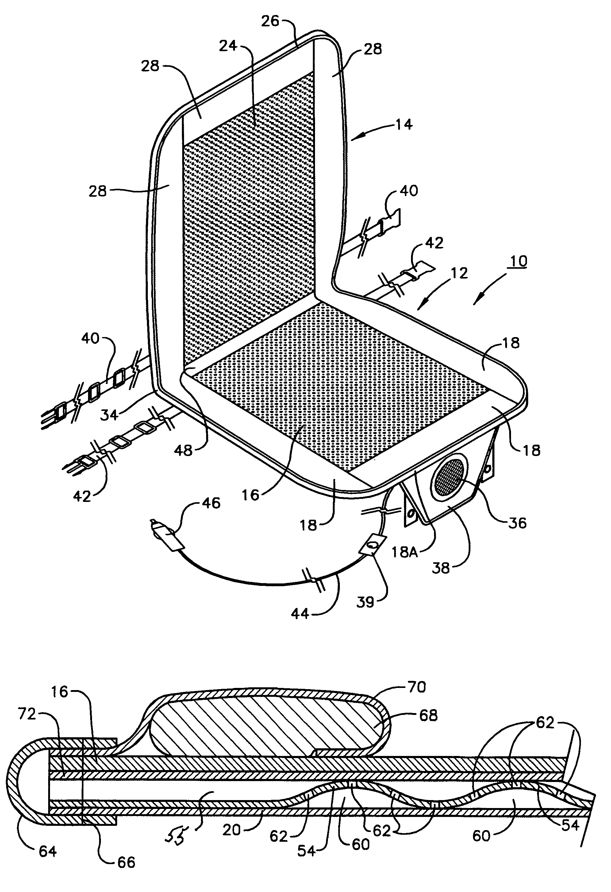
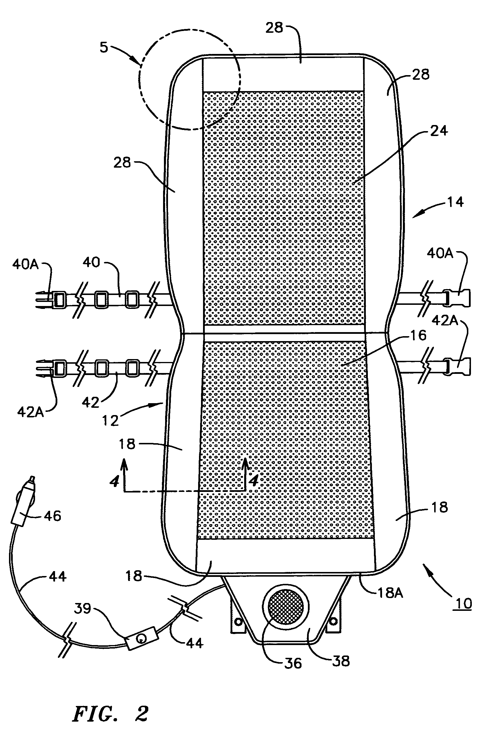
[0013]Referring now to FIG. 1, the seat cushion 10 of the present invention comprises: a seat portion 12; a back portion 14; seat portion 12 having a front surface 16, a perimeter 18, a rear surface 20 (best seen in FIGS. 3 and 4), and an interior 22 between front surface 16 and rear surface 20 (best seen in FIG. 4); back portion 14 having a front surface 24, a top 26, a perimeter 28, a rear surface 30 (best seen in FIGS. 3 and 4), a bottom 34 and an interior 32 between front surface 24 and rear surface 30 (best seen in FIG. 4); and an integral fan 36 mounted in a tongue 38 extending from the front perimeter 18A of seat portion 12. Belts 40 and 42 incorporating latches 40A and 42A are attached to perimeters 28 and 18 of back and seat portions 14 and 12 respectively for fastening seat cushion 10 to an existing automobile or other seat / chair (not shown). An electrical connecting cord 44 is electrically attached to fan 36 is to provide power to fan 36. Preferably, electrical connecting...


PUM


Abstract

A portable seat cushion comprising: A) a seat portion; B) a back portion; and C) an integral fan that circulates air through the seat and back portions, the front portion having a front surface, a perimeter, a rear surface and an interior between the rear and front surfaces and the back portion having a front surface, a top, a bottom, a perimeter, a rear surface and an interior between the rear surface and the front surface, the seat and back portions being joined by a flexible connection that permits the seat and back portions to rotate relative to each other and provides a mechanism for the passage of air from the seat portion to the back portion. The rear surfaces and perimeters of each of the seat and back portions is relatively air impermeable while the front surfaces of these members is air permeable. The interior of each of the back and seat portions includes a semi-rigid undulating member that defines passages for the movement of air from the incorporated fan to the seat and back portions and to the front surfaces of the seat and back portions through apertures therein.

Description

FIELD OF THE INVENTION[0001]The present invention relates to portable seat cooling devices and more particularly to such devices that can be used in an automobile to provide localized cooling for the seat and back areas of a user.BACKGROUND OF THE INVENTION[0002]While conventional automotive air conditioning provides cooling to the “front” portions of an individual on hot summer days, the back and seat portions of an individual driver or passenger receives little relief from such conventional general automotive interior cooling because of the lack of exposure of such areas of the body to the air conditioned environment. Thus, the provision of cooling to the seat and back areas of, for example, an automobile driver or passenger during hot weather has been the subject of much development.[0003]U.S. Pat. No. 6,189,967 to Short issued Feb. 20, 2001 describes a portable air cooled seat cushion provided with a fan that produces an air stream directed to the interior of the portable cushio...

Claims


Application Information

Patent Timeline
IPC IPC(8): A47C7/74
CPCA47C7/74B60N2/6027B60N2/5635
Inventor WONG, PETER H.
Owner WONG PETER H
Learn More