
Toggle and toggle connection assembly

a technology of toggle connection and toggle, which is applied in the direction of conveyor parts, slitting machines, earthwork drilling and mining, etc., can solve the problems of extremely high wear and tear of toggles and toggle pockets, and achieve the effect of simple assembly of toggles and high angular mobility

Active Publication Date: 2006-07-04
CATERPILLAR INC
View PDF12 Cites 5 Cited by
  • Summary
  • Abstract
  • Description
  • Claims
  • Application Information

AI Technical Summary

Benefits of technology

[0006]Thus, the problem to be solved by the present invention is to make available a toggle and a toggle connection with which high axial forces can be transmitted while ensuring high angular mobility and simple assembly of the toggles.
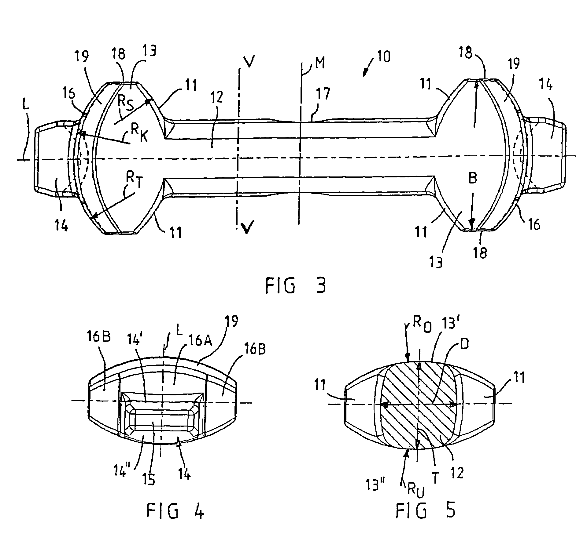
[0007]This problem with respect to the toggle is solved in that the shoulder areas have a spherical design, in particular a rounded spherical design. Because of the spherical design of the shoulder area and the thus resultant punctiform or linear contact surface between the shoulder areas on the toggle heads and the associated stop faces on the toggle pockets, the vertical mobility of adjoining conveyor pans necessary to compensate for troughs or saddles in the sill of the seam is improved and, at the same time, the transmission of axial tensile forces to the toggle heads is optimized. Because of the defined force transmission of the transmitted forces between the shoulder areas and the stop faces, surface pressures are avoided in underground mining operations.
[0008]In a preferred embodiment, both toggle heads, on the head end facing away from the shaft, have a bolt tongue—which projects in the axial direction and the cross section or thickness of which relative to the toggle head is tapered—and / or the toggle heads, shoulder areas and bolt tongues are symmetrically designed about the center of the shaft. Errors in the assembly of the toggle due to erroneous positioning of the toggle in the toggle pockets are avoided because the construction provides for a symmetrical design. In a preferred embodiment, the radius of curvature of the head end on jointing surfaces on the sides of the bolt tongues may be of identical size as, or smaller than, the radius of curvature of the shoulder areas. The radius of curvature of the jointing surface of the head end above the bolt tongue may differ from the radius of curvature on the jointing surfaces on the sides of the bolt tongue and may be as large or substantially as large as the radius of curvature on the shoulder area. Because of the smaller radius of curvature on the head end along the sides of the bolt tongues, pressures on the head end are avoided even if there are maximum vertical angular differences between adjacent conveyor pans.
[0010]In an especially preferred embodiment, the toggle heads—at least on the lower side of the toggle heads and / or also on the upper side of the toggle heads—are curved, especially rounded, throughout the width, i.e., from the surface of one side to that of the other side. In this case, the radius of curvature on the lower and upper side of the toggle heads can especially be the same as the radius of curvature on the shoulder areas. Because of the rounded regions of the toggle heads throughout the width, the vertical and horizontal mobility of adjacent pans or guide troughs is additionally improved. The radius of curvature on the shoulder areas and / or jointing surfaces can preferably be smaller than the distance between the lateral surfaces on the toggle heads and larger than the maximum depth of the shaft and the maximum depth of the toggle heads.
[0011]When mounting the toggle according to the present invention, it is useful if on the upper side of the bolt tongues and on the lower side of the bolt tongues, the bolt tongues taper conically toward their front ends. The upper side of the bolt tongues and the lower side of the bolt tongues can be designed so as to be substantially plane across the width of the bolt tongues. It is also preferable if the toggle shaft has an oval cross section and / or if the toggle shaft at its midpoint has a tapered area that acts as a predetermined breaking point, thus ensuring that even on excessive wear and tear on the toggle connection, damage to the conveyor pans and the toggle pockets attached thereto can be avoided because of the predetermined breaking points in the toggle.

Problems solved by technology

In underground mining operations, the toggles and the toggle pockets are subjected to extremely high wear.

Method used


Image

  • Toggle and toggle connection assembly
  • Toggle and toggle connection assembly
  • Toggle and toggle connection assembly

Examples


Embodiment Construction

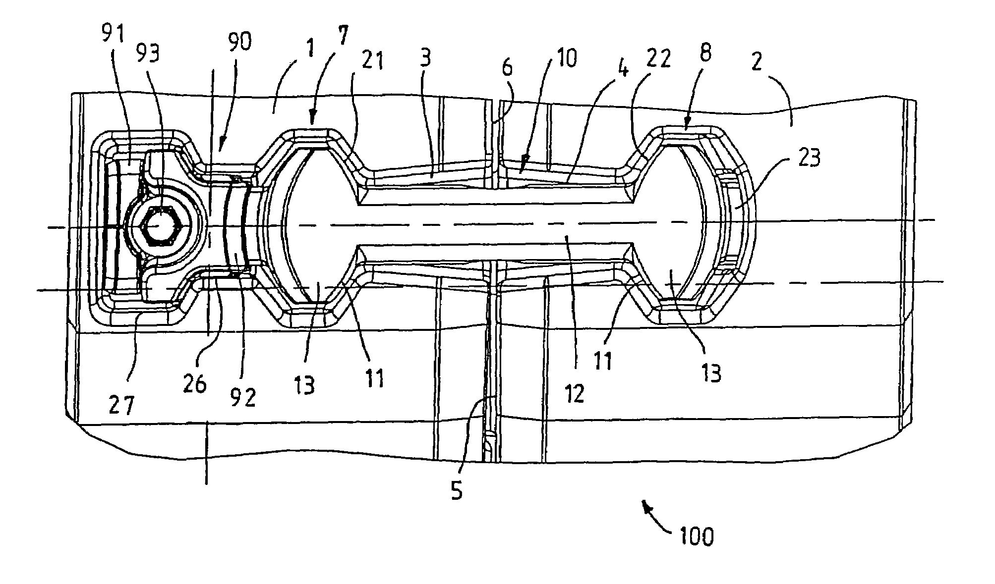
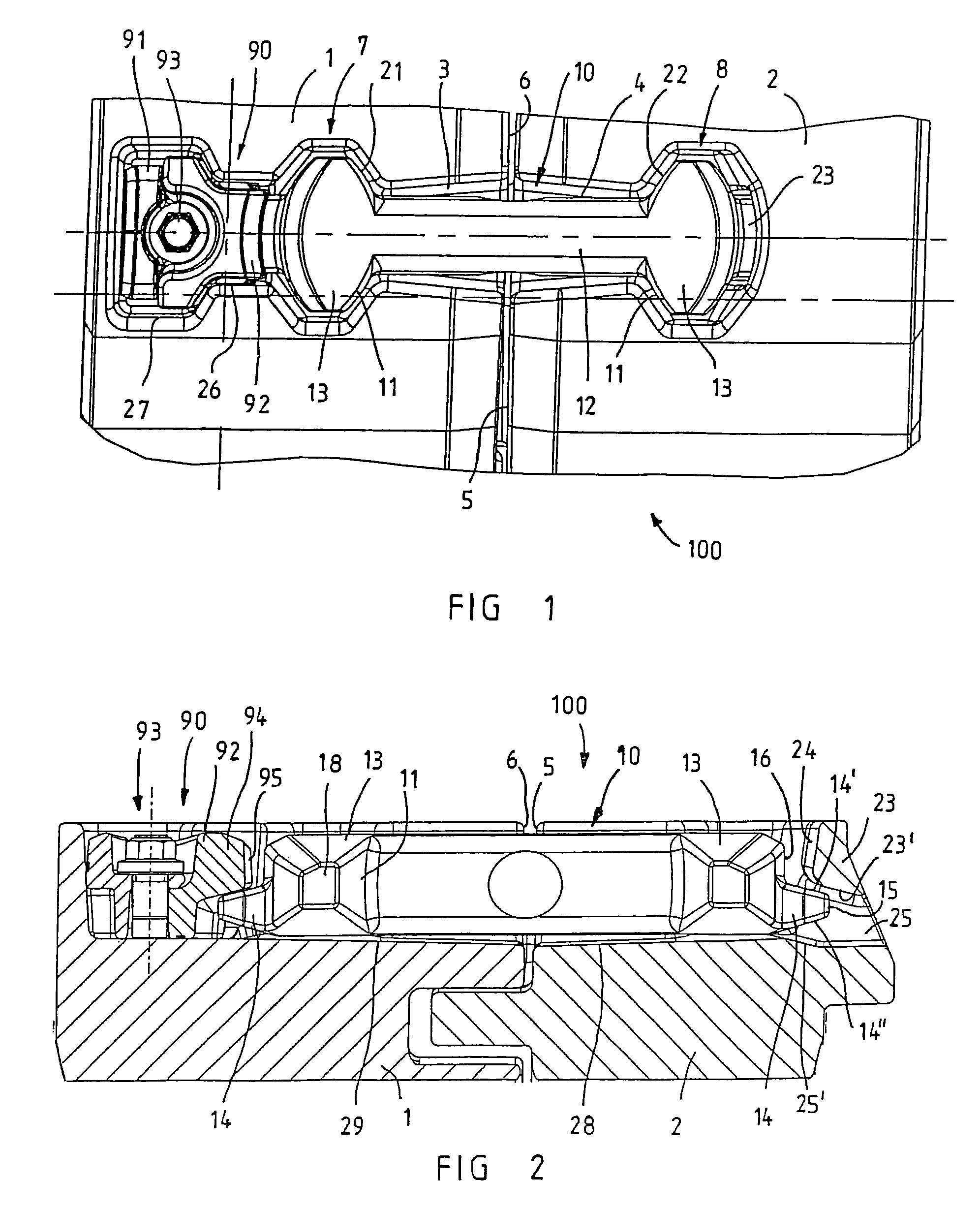
[0021]FIGS. 1 and 2 show a toggle connection assembly, which in its entirety is designated by the reference numeral 100, for connecting conveyor pans (not shown) of a chain scraper conveyor or guide troughs (not shown) of a mining machine guide used in underground mining operations in a tension-proof and angularly movable manner with one another. Toggle connection assembly 100 comprises a first toggle pocket 1 and a second toggle pocket 2 which, on the associated pans and troughs, are joined either by welding them on as welded pieces or by directly casting them on. Each of the two toggle pockets 1,2 forms a toggle holding pocket 3 and 4 for one of the two halves of the toggle, which in its entirety is designated by reference numeral 10. Each toggle holding pocket comprises a shaft holding section which conically tapers beginning on the front sides of toggle pockets 5 and 6, which shaft holding section ends in a head holding section 7 and 8. Relative to each respectively other toggle...


PUM


Abstract

Toggles are disclosed for toggle connections of conveyor pans of a chain scraper conveyor or conveyor troughs of a mining machine guide. In providing a toggle and a toggle connection, with which high axial forces can be transmitted while, at the same time, maintaining high angular mobility of the pans and troughs, shoulder areas of the toggle are designed so as to be spherical. Because of the spherical design of the shoulder areas, the vertical mobility of adjoining conveyor pans is improved while at the same time the transmission of axial tensile forces to the toggle heads is optimized.

Description

FIELD OF THE INVENTION[0001]The present invention relates to a toggle or a coupling component for a toggle connection assembly adapted for use with conveyor pans of a chain scraper conveyor or for guide troughs of a mining machine guide. In particular, the present invention relates to a toggle having two toggle heads which are connected in one piece via a shaft, the width of which is tapered. The toggle heads, on the side facing the shaft, have shoulder areas that slope downwardly in the direction of the shaft. The present invention also relates to a toggle connection that utilizes a suitable toggle and corresponding toggle pockets that are defined in the pans and troughs. The toggle, having the toggle heads that are connected in one piece via the shaft, can be inserted into the toggle pockets. The toggle pockets have downwardly inclined stop faces which interact with shoulder areas on the toggle heads of the toggle.BACKGROUND OF THE INVENTION[0002]In underground mining operations, ...

Claims


Application Information

Patent Timeline
IPC IPC(8): B65G19/28B65G21/00E21C27/00E21F13/08
CPCB65G19/287
Inventor KLABISCH, ADAMDUHNKE, KLAUSHESSE, NORBERTSIEPENKORT, GERHARDTILLESSEN, UWE
Owner CATERPILLAR INC
Learn More