
Video server for video distribution system

a video server and video technology, applied in the field of video servers, can solve the problems of difficult to pass multicast information through, general blockage of multicast information, limited multicast-based transmission effect, etc., and achieve the effect of reducing transmission costs

Inactive Publication Date: 2006-06-27
HITACHI LTD
View PDF10 Cites 44 Cited by
  • Summary
  • Abstract
  • Description
  • Claims
  • Application Information

AI Technical Summary

Benefits of technology

[0010]It is an object of the present invention to provide a video server for a video distribution system which is capable of solving the above-mentioned problems, and transmitting the same video from a video server to a plurality of terminals utilizing the multi-cast to reduce the transmission cost even when firewalls are interposed between the video server and the terminals.

Problems solved by technology

However, the effectiveness of the multicast-based transmission is limited only to those paths which support the multicast from an origination to all terminals belonging to a host group.
Multicast information is generally blocked by the firewall.
However, it is quite difficult to pass multicast information through in the current Internet in which firewalls are installed everywhere and managed independently by different organizations.
In this event, the amount of information transmitted from the video server to the terminals is increased in proportion to the number of receiving terminals, resulting in a problem of a higher transmission cost.
On the other hand, many of protocols for passing information through a firewall are inherently intended for file transfer, so that although they can transmit information without errors, they do not guarantee when the information will arrive at a particular terminal.

Method used


Image

  • Video server for video distribution system
  • Video server for video distribution system
  • Video server for video distribution system

Examples


Embodiment Construction

(1) System Configuration

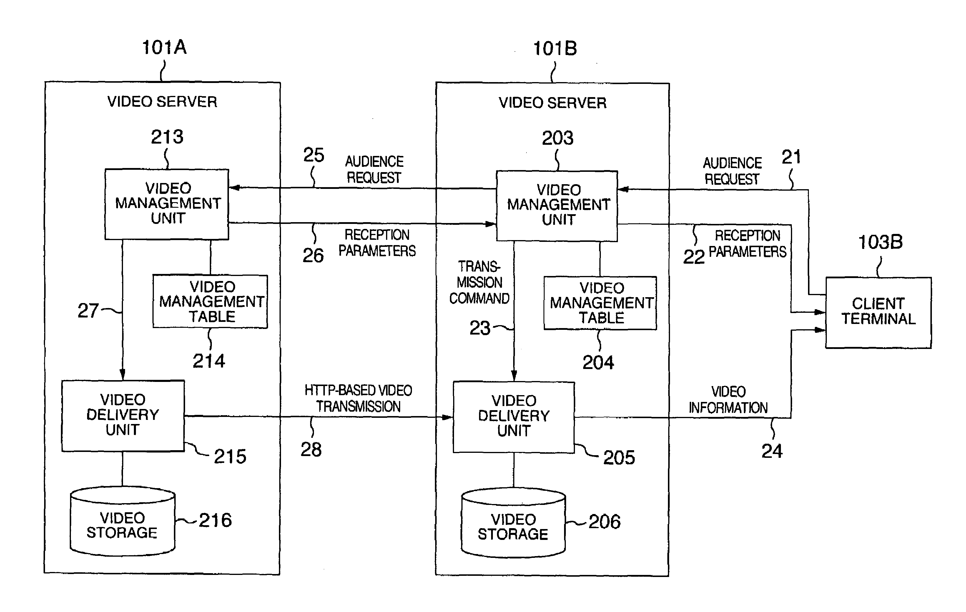
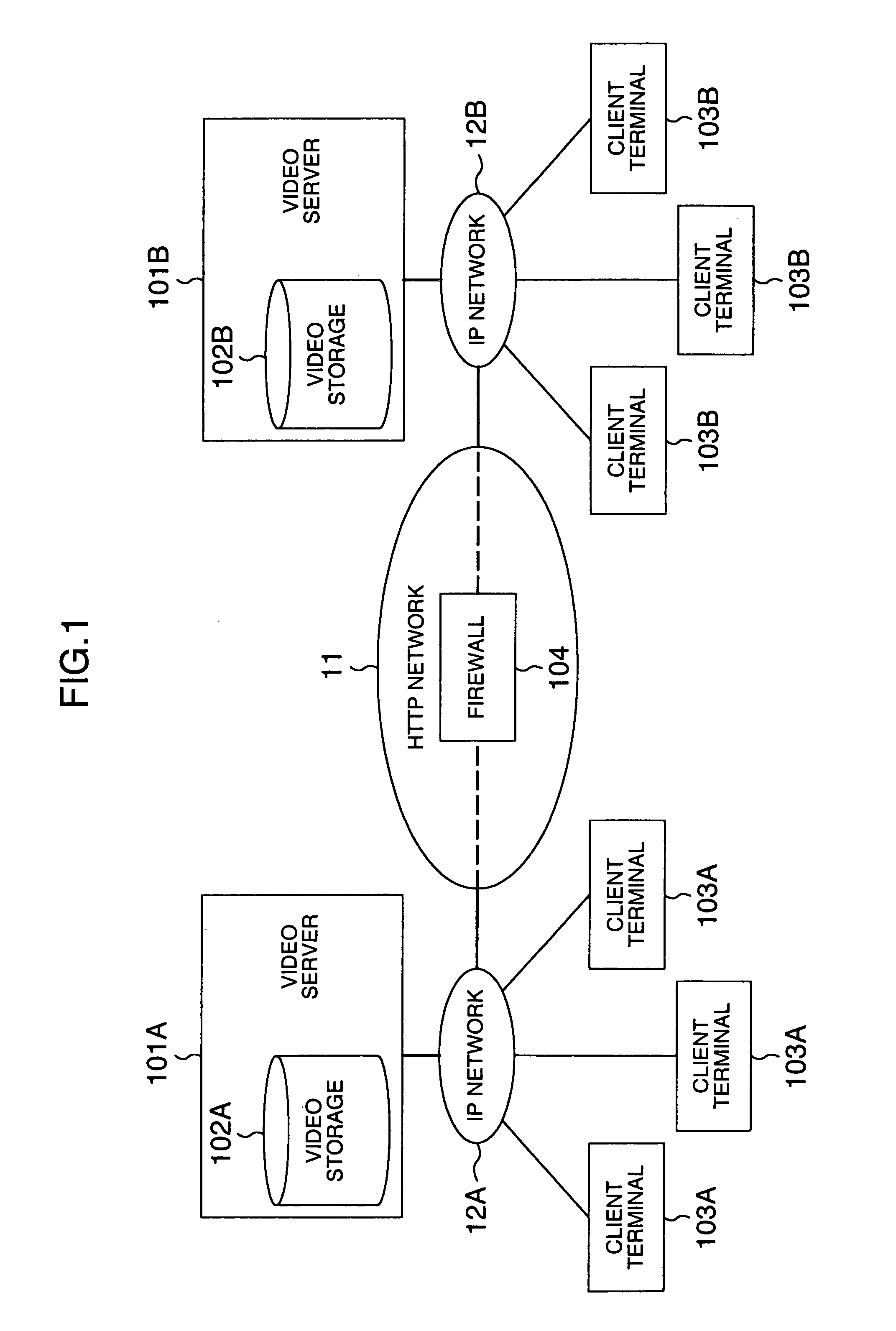
[0022]FIG. 1 illustrates an example of a video distribution system in which two video servers according to the present invention are connected through a transmission path which does not allow IP multicast to pass therethrough.

[0023]A video content stored in a video storage 102A of a video server 101A can be transmitted simultaneously to client terminals 103A through an IP network 12A using an IP multicast transmission scheme.

[0024]However, as to client terminals 103B connected to an IP network 12B, IP multicast based transmission cannot be realized from the video server 101A to the client terminal 103B, though connected to the network 12B, because a network connecting the IP network 12A and the IP network 12B has a firewall 104 interposed therebetween and serves as a network dedicated to HTTP.

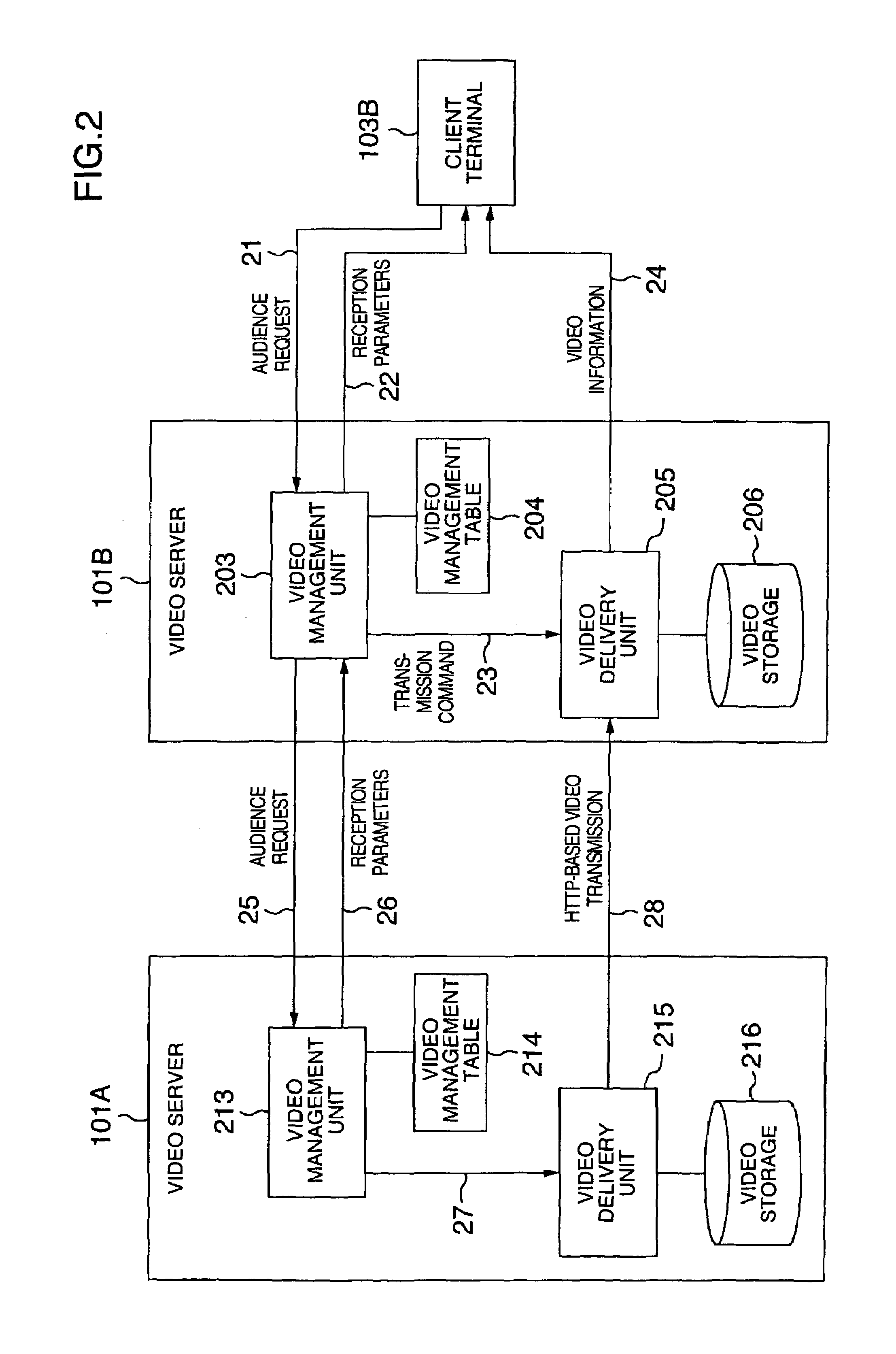
[0025]To eliminate this inconvenience, the present invention transmits image information using the HTTP protocol only when the image information is passed through an HTT...


PUM


Abstract

A video server for distributing a digitized video content includes a unit for determining whether or not a video content requested from a terminal is stored in the video server, a unit for issuing a transmission request to another server for transmitting the video thereto in accordance with the HTTP protocol when the video content requested from the terminal is not stored in the video server, and a unit for receiving the video content transmitted from the other video server in accordance with the HTTP protocol, and transmitting the video content to the terminal in accordance with IP multicast or HTTP protocol.

Description

CROSS-REFERENCE TO RELATED APPLICATION[0001]This application relates to U.S. application Ser. No. 09 / 764,377 filed on Jan. 19, 2001 based on Japanese Application 2000-021977, and assigned to the present assignee. The content of that application is incorporated herein by reference.BACKGROUND OF THE INVENTION[0002]The present invention relates to a video server for transmitting a video signal in parallel to a plurality of locations using the Internet protocol, and more particularly, to a video server for a video distribution system which enables transmission of a video signal through a transmission path, which cannot use IP multicast, through protocol conversion.[0003]Simultaneous transmission of a signal such as a video signal to multiple locations, utilizing a protocol such as the Internet protocol, is referred to as “multicast,” and a number of methods for realizing the multicast have already been proposed, with some of such methods already brought into practical use. A representat...

Claims


Application Information

Patent Timeline
Patent Type & Authority Patents(United States)
IPC IPC(8): G06F15/16G06F13/00H04L12/18H04L45/16H04N7/173H04N21/643H04N21/647
CPCH04N21/23H04N21/21
Inventor SHIBATA, KOICHIIGAWA, MASARUMORITA, KOICHISAKAMOTO, SHUICHI
Owner HITACHI LTD
Learn More