Submarine branching unit having asymmetrical architecture

a branching unit and symmetrical technology, applied in relay terminal arrangements, relay details, transmission, etc., can solve the problems of affecting the operation of submarine branching units, the failure of the relay and the connection of the main cable to sea earth, and the failure of the conventional circuit of power feed equipment in submarine branching units to ensure the operation of good feed paths

Inactive Publication Date: 2006-06-27
PIRELLI CAVI E SISTEMI SPA
View PDF11 Cites 5 Cited by
  • Summary
  • Abstract
  • Description
  • Claims
  • Application Information

AI Technical Summary

Benefits of technology

[0020]Applicants have discovered that an asymmetrical configuration for a submarine branching unit that uses bypass relays and directional relays can help to avoid the problem of arcing that can occur when relay contacts actuate under high current pulse conditions.

Problems solved by technology

Switching the spur cable to sea earth (typically the sea water) can cause a rapid discharge, which may damage contacts and relays with the branching unit.
An avalanche effect could take place that causes the main cable to discharge across the contact gap with large amperage, leading to imminent failure of the relay and connection of the main cable to sea earth.
Applicants have discovered that conventional circuits for power feed equipment in submarine branching units do not insure continued operation of good feed paths following the failure of a faulted feed path.
Applicants have also discovered that conventional circuits do not provide adequate protection of relay contacts against possible arcing damage due to high current pulses as a consequence of cable discharge.

Method used


Image

  • Submarine branching unit having asymmetrical architecture
  • Submarine branching unit having asymmetrical architecture
  • Submarine branching unit having asymmetrical architecture

Examples


first embodiment

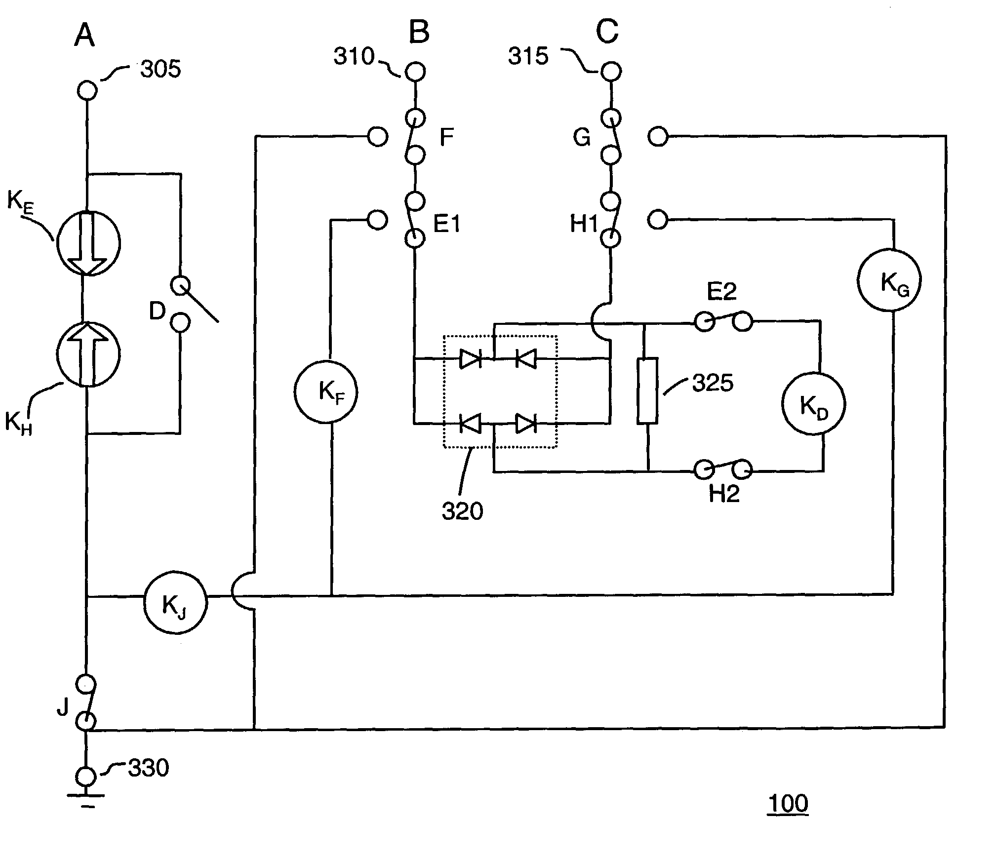
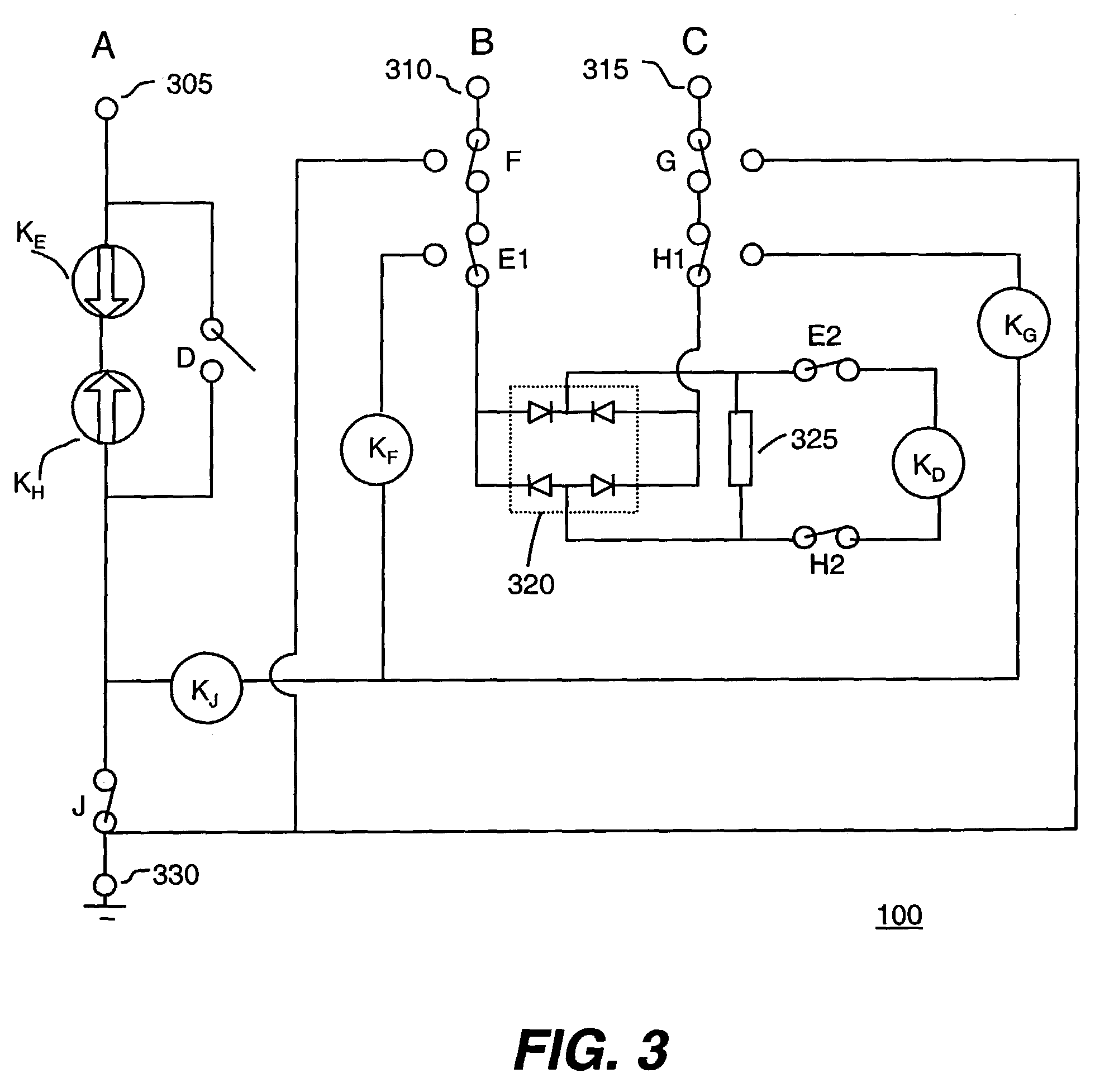
[0046]Branching unit 100 according to the present invention includes circuitry with relays KD, KE, KF, KG, KH, and KJ, whose coils are depicted in FIG. 3 as circles. The contacts of the relays are designated with corresponding letters. For instance, contact D in FIG. 3 is controlled by the coil of relay KD. Likewise, contacts E1 and E2 are both controlled by the coil of relay KE. Shown in its quiescent state, branching unit 100 of FIG. 3 is illustrated with all relay contacts in their “normal” state, i.e., the state where the contact lies when its relay is de-energized.

[0047]Each relay has a threshold pull-in current above which a magnetic field will be produced in its coil sufficient to energize the relay and to cause the contact to switch position. In addition, all relays shown in the diagram are non-latching relays, meaning that the contacts return to their original position when the coil changes from an energized to a de-energized state. The change from an energized state to a d...

second embodiment

[0061]In the present invention, additional relays and contacts are included to protect the contacts of branching unit 100 from faults, either short circuits or open circuits. This alternative embodiment minimizes the potential for damage to relay contacts that may occur if the contacts are not firmly closed and high currents pass through them when a fault exists on the line.

[0062]FIG. 8 is a schematic diagram of the second embodiment of the present invention showing a branching unit 900 that includes fault protection. Branching unit 900 of FIG. 8 adds relays KL, KM, KN, and KO and affiliated switches L, M1–M4, N1–N4, and O to the configuration of branching unit 100 of FIGS. 3–7. For the main trunk in the original configuration, which is formed of the cables attached to terminals 310 and 315, the additional switches M2 and N2 are naturally in a closed position so that a current such as IBC can be established between landing points B and C. When relay KD becomes energized from current...


PUM


Abstract

A branching unit for use in submarine systems that includes a ground termination; first, second, and third cable terminations each coupled to a power feed line of a respective submarine cable; a re-configuration relay in series between the first cable termination and the ground termination, the re-configuration relay being unidirectional and having at least one contact positioned in series between the second and third terminations, the at least one contact being closed when the re-configuration relay is de-energized; and a bypass relay in series between the second and third cable terminations, the bypass relay having a contact positioned in parallel with the reconfiguration relay and being open when the bypass relay is de-energized.

Description

CROSS REFERENCE TO RELATED APPLICATIONS[0001]This application claims the benefit of U.S. Provisional Application No. 60 / 342,850, filed Dec. 28, 2001, the content of which is incorporated herein by reference, and claims the right to priority based on European Application No. 01130187.6, filed Dec. 19, 2001, the content of which is incorporated herein by reference.BACKGROUND OF THE INVENTION[0002]The present invention relates to a submarine branching unit of an optical submarine cable communication system. More particularly, the present invention relates to a submarine branching unit having an asymmetrical architecture with a switching system designed to enhance the life of relay contacts by switching at zero current conditions.[0003]Underwater or submarine cable systems were originally designed to provide a telecommunications link between two landing points separated by a body of water, such as between France and England. Optical fiber within the submarine cable could carry high band...

Claims


Application Information

Patent Timeline
Patent Type & Authority Patents(United States)
IPC IPC(8): H01H45/00H01H45/14H02H7/00H04B3/44
CPCH04B3/44
Inventor BIANCHI, GIUSEPPE
Owner PIRELLI CAVI E SISTEMI SPA
Why Eureka
Try Eureka