
Sensor and method for detecting very low frequency acoustic signals

a sensor technology, applied in the field of very low frequency acoustic signal detection sensors, can solve the problems of sensors becoming detached from the patient, affecting the patient's daily life,

Inactive Publication Date: 2006-06-27
ILIFE SOLUTIONS
View PDF8 Cites 13 Cited by
  • Summary
  • Abstract
  • Description
  • Claims
  • Application Information

AI Technical Summary

Benefits of technology

[0021]Prior art acoustic sensors directly detect higher frequency sounds that are made by the lungs during respiration or by the heart during cardiac activity. The sensor of the present invention, however, obtains information by detecting the very low frequency signals caused by the motion of the chest during respiration or cardiac activity. Almost all of the noise components in an acoustic signal have frequencies that are above the very low frequency range. By using the method of the present invention to exclude the higher frequencies of sound (and noise), the sensor of the present invention eliminates almost all the noise artifacts from the acoustic signal.
[0026]It is also an object of the present invention to provide an improved sensor and method for a physiological condition monitor capable of detecting very low frequency acoustic signals indicative of physiological conditions where the sensor is not coupled directly to the skin of the person being monitored.
[0027]It is also an object of the present invention to provide an improved sensor and method for a physiological condition monitor capable of detecting very low frequency acoustic signals that are indicative of physiological conditions where the sensor is capable of detecting such signals through the clothes of the person being monitored.

Problems solved by technology

When a person exhibits apnea, bradycardia or tachycardia a life threatening condition very likely exists.
The wires attached to the patient restrict the patient's movements and frequently become tangled as the patient moves.
The tangling of the wires can also result in the sensors becoming detached from the patient.
Acoustic signals normally contain noise artifacts.
This is due to the fact most noise artifacts occur at frequencies that are higher than these frequencies.

Method used


Image

  • Sensor and method for detecting very low frequency acoustic signals
  • Sensor and method for detecting very low frequency acoustic signals
  • Sensor and method for detecting very low frequency acoustic signals

Examples


Embodiment Construction

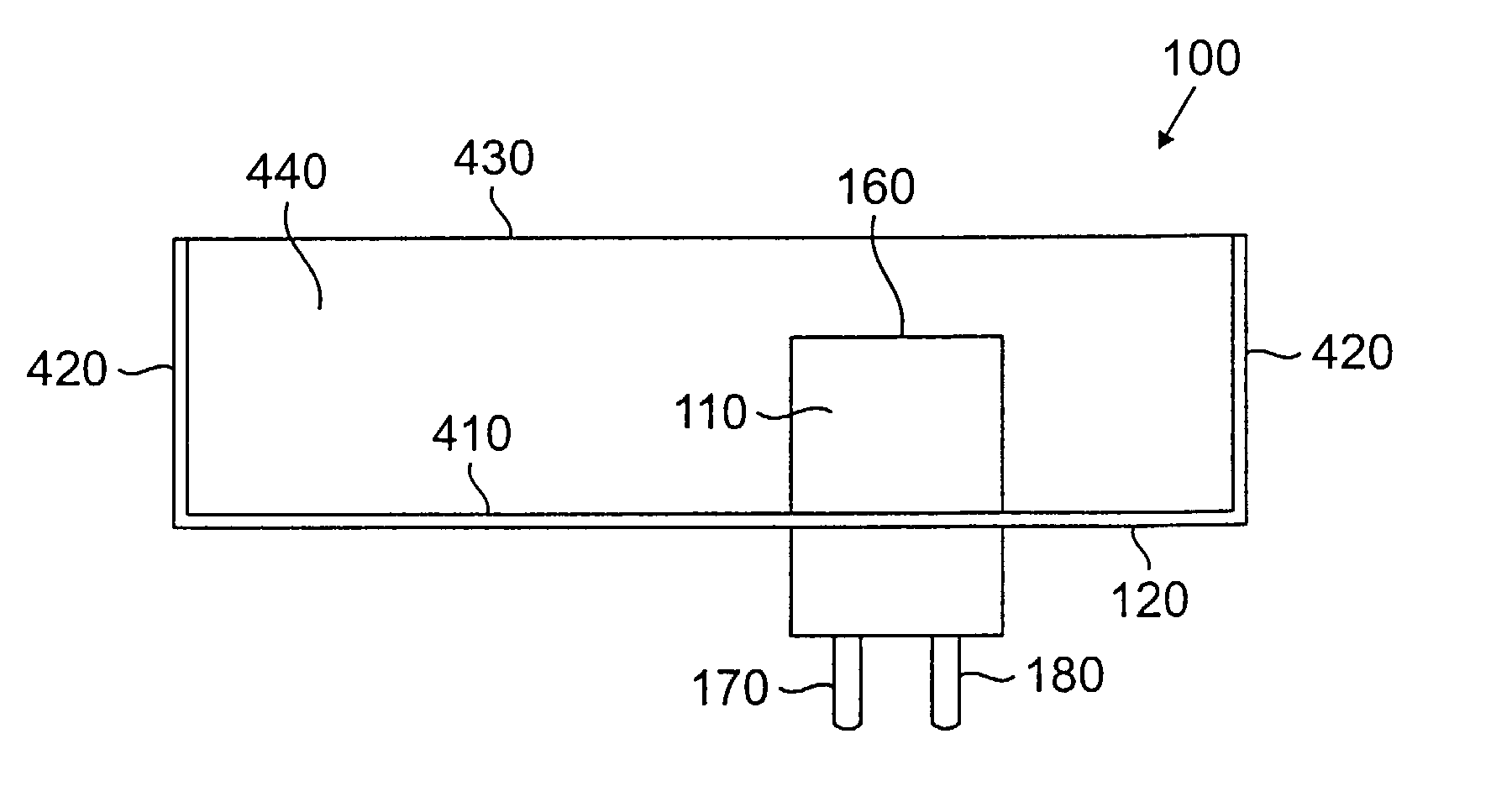
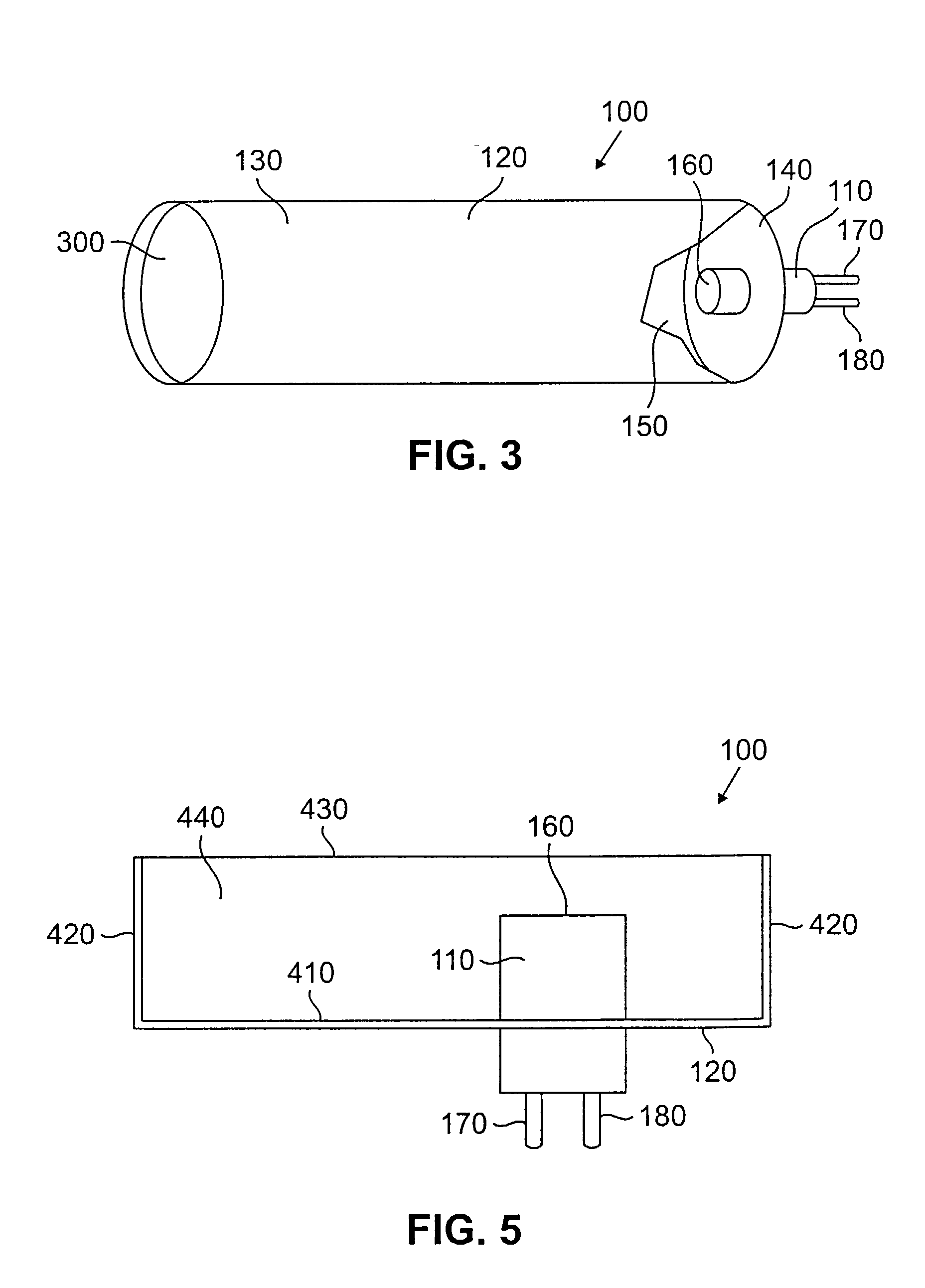
[0038]FIGS. 1 and 5, discussed below, and the various embodiments used to describe the principles of the present invention in this patent document are by way of illustration only and should not be construed in any way to limit the scope of the invention. Those skilled in the art will understand that the principles of the present invention may be implemented in a suitably modified sensor.

[0039]FIG. 1 is a partially cutaway view showing an advantageous embodiment of sensor 100 of the present invention. Sensor 100 comprises a chamber 120 and a microphone 110. In this embodiment chamber 120 comprises a hollow tube having side walls 130 and end walls 140 that form cavity 150 within chamber 120. Cavity 150 of chamber 120 is filled with a fluid (not shown). The connections between side walls 130 and end walls 140 are sealed to prevent the escape of the fluid from cavity 150. The fluid may be either a liquid or a gas. In most instances the fluid that is used is air.

[0040]When the fluid that...


PUM


Abstract

There is disclosed a sensor and method for detecting very low frequency acoustic signals. The sensor is capable of detecting low frequency acoustic signals in the frequency range of one tenth Hertz to thirty Hertz. The sensor comprises a chamber having portions that form a cavity and a low frequency microphone placed within the cavity. An alternate embodiment of the invention comprises a chamber having portions that form a resonant cavity, a low frequency microphone placed within the resonant cavity, and a membrane that covers the resonant cavity. Low frequency acoustic signals that are incident on the membrane cause the membrane to move and amplify the acoustic signals within the resonant cavity.

Description

[0001]This application is a continuation of prior U.S. application Ser. No. 09 / 536,104 filed on Mar. 24, 2000 now U.S. Pat. No. 6,416,483.RELATED APPLICATIONS[0002]A related patent application by M. E. Halleck and M. D. Halleck has been filed concurrently with this patent application entitled “Apparatus and Method for Detecting Very Low Frequency Acoustic Signals” application Ser. No. 09 / 534,813. A related patent application by M. E. Halleck, M. D. Halleck, M. L. Lehrman and A. R. Owen has been filed concurrently with this patent application entitled “Physiological Condition Monitors Utilizing Very Low Frequency Acoustic Signals” application Ser. No. 09 / 536,093. A related patent application by M. E. Halleck and M. D. Halleck has been filed concurrently with this patent application entitled “System and Method for Remotely Monitoring At Least One Physiological Characteristic of a Child” application Ser. No. 09 / 536,076. Another related patent application by M. E. Halleck, M. D. Halleck...

Claims


Application Information

Patent Timeline
IPC IPC(8): A61B7/00
CPCA61B7/003
Inventor HALLECK, MICHAEL E.HALLECK, MICHAEL D.LEHRMAN, MICHAEL L.
Owner ILIFE SOLUTIONS
Learn More