
Laser light beam guiding device on a stone cutter

a laser light beam and stone cutter technology, applied in the field of laser light beam guiding device on stone cutters, can solve the problems of wasting a lot of time and labor, not being as accurate as expected, and the old method has been proved too rough, so as to achieve precise and rapid cutting activity.

Inactive Publication Date: 2006-06-27
CHEN YUEH TING
View PDF3 Cites 44 Cited by
  • Summary
  • Abstract
  • Description
  • Claims
  • Application Information

AI Technical Summary

Benefits of technology

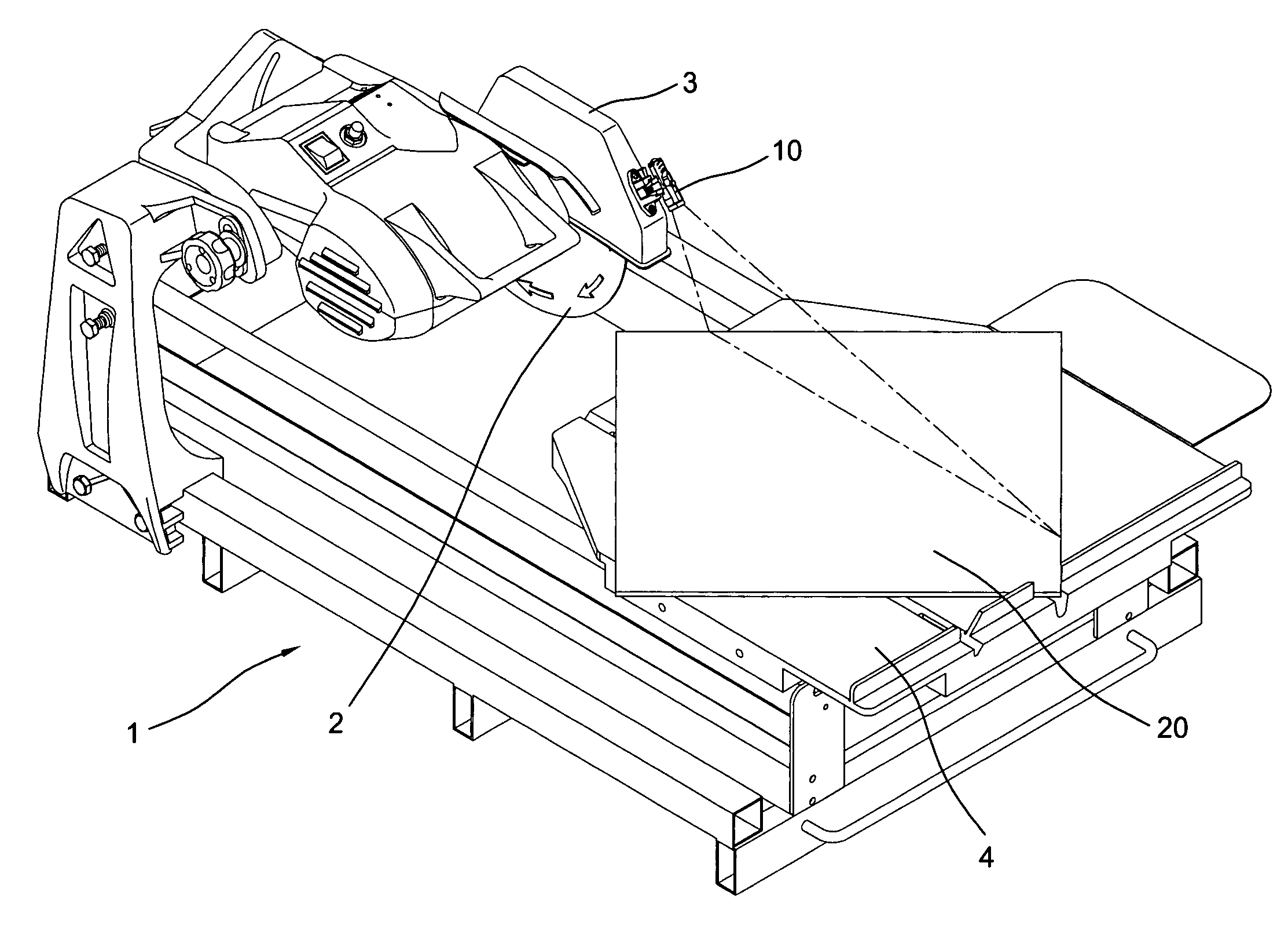
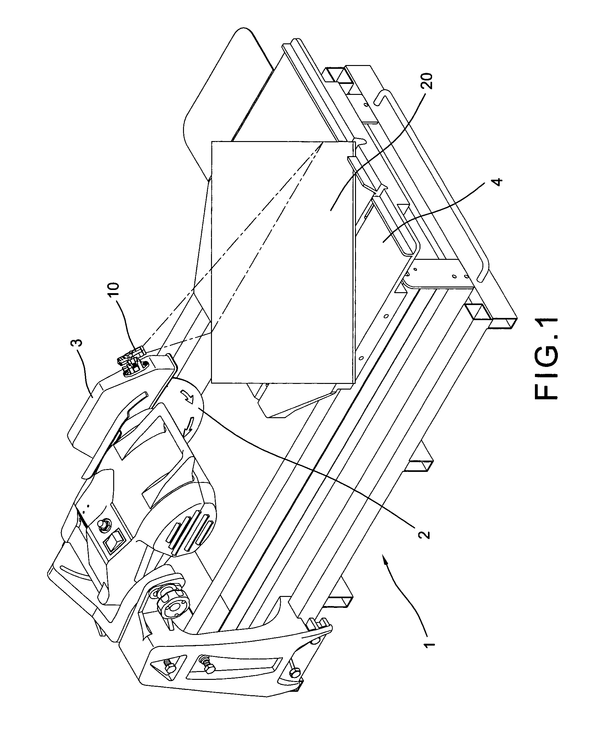
[0003]The present invention has a main object to provide a laser light beam guiding device on a stone cutter which utilizes the laser light beam projecting on the surface of a working piece for facilitating the saw blade to follow to implement a precise and rapid cutting activity.
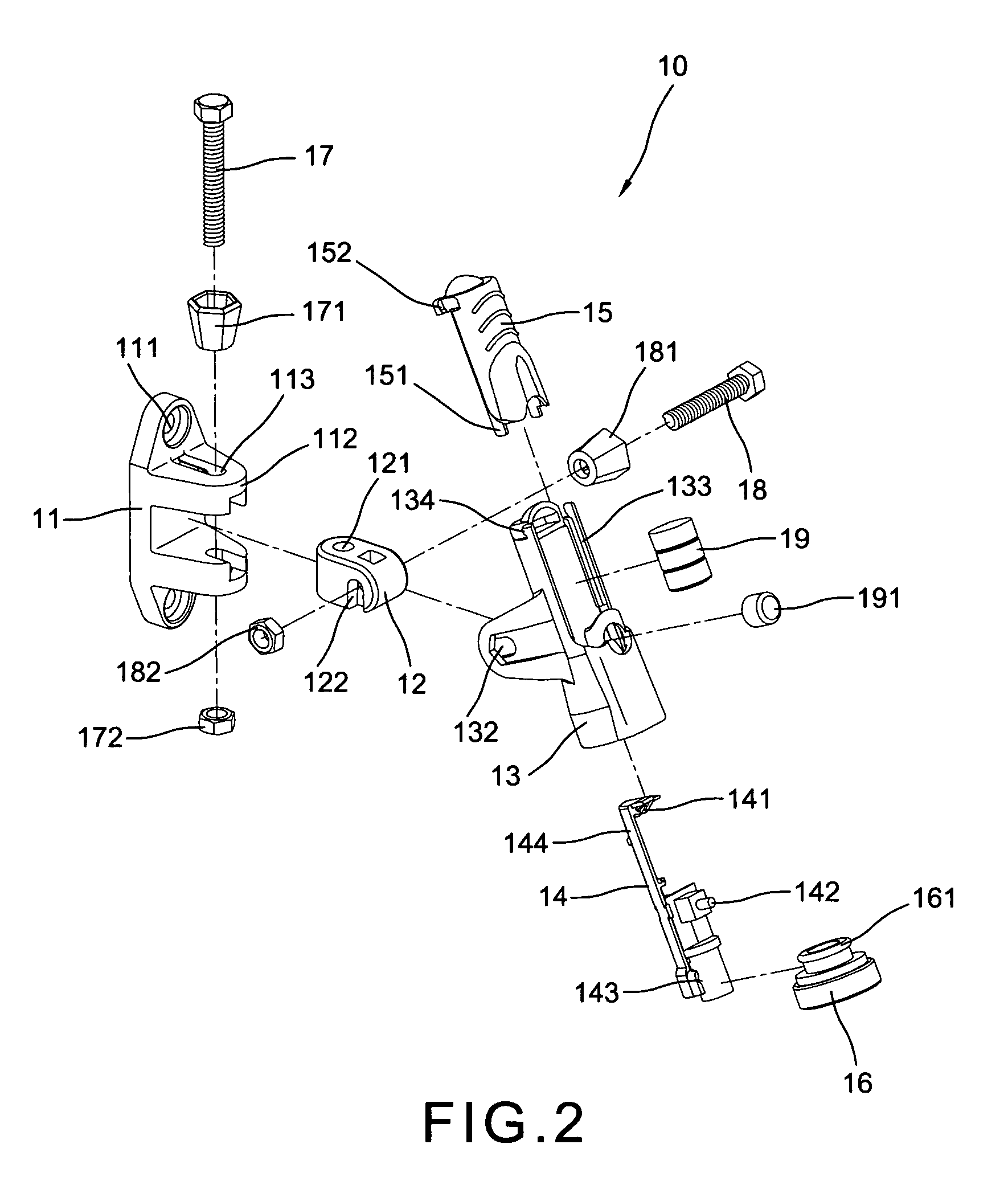
[0006]The laser light beam guiding device has a tubular main body, a battery chamber in the body, a laser projector at the front end, a tubular sleeve on the rear end, a switch button on a top and a pair of perforated fin plates pivoted to a lug of an oblong seat which is secured to the blade guard of the stone cutter. So that the laser light beam device is able to turn vertically and laterally to quickly fine out an exact cutting line on the working piece for the saw blade to follow up.

Problems solved by technology

This old method has been proved too rough and wasting a lot of time and labor.
Besides, the result is not so accurate as expected so as to cause a great lost.

Method used


Image

  • Laser light beam guiding device on a stone cutter
  • Laser light beam guiding device on a stone cutter
  • Laser light beam guiding device on a stone cutter

Examples


Embodiment Construction

[0015]With reference to the drawings and initiated from FIGS. 1 to 4, the laser light beam guiding device on a stone cutter of the present invention comprises a laser light beam guiding device 10 secured on a front top of the guard 3 of a saw blade 2 of a stone cutter 1 which includes a slidable platform 4 with a working piece 20 on the platform 4.

[0016]The laser light beam guiding device 10 comprises an oblong seat 11 having a pair of through holes 111 respectively formed in two end for securing the seat 11 to a front top of the guard 3 by screws, a lug 112 projected outward from the center of one side having an oblong through hole 113 in a lateral side and a pair of concaves symmetrically formed in inner side for engaging within a pivot block 12 which has a vertical through hole 121 engaged with the oblong through hole 113 of the lug 112 and rotataly secured by a bolt 17 and a pair of nut 171 and 172 and a horizontal slot 122 in a bottom, a tubular main body 13 including a pair of...


PUM

PropertyMeasurementUnit
conductiveaaaaaaaaaa

Abstract

A laser light beam guiding device on a stone cutter includes a tubular main body pivoted to a lug of a seat which is secured to a front top of a blade guard of the stone cutter, a battery chamber in the main body controlled by a switch button on the top, a tubular sleeve on the rear portion of the main body and a laser projector rotatably engaged with the front end of the main body to emit the light beam on a working piece to decide a cutting line for the saw blade to follow up.

Description

BACKGROUND OF THE INVENTION[0001]The present invention relates to stone cutters and more particularly to a laser light beam guiding device on a stone cutter which utilizes the laser light flux to calibrate a cutting line for the saw blade to follow to implement a precise cutting activity.[0002]As we know that a stone cutter being cutting a tile has to previously decide a precise cutting line for the tile on the sliding leaf of a stone cutter for the saw blade to flow. Nodaway, most of the operator uses a ruler to measure a culling line on the tile before the saw blade begins to cutting. This old method has been proved too rough and wasting a lot of time and labor. Besides, the result is not so accurate as expected so as to cause a great lost.SUMMARY OF THE PRESENT INVENTION[0003]The present invention has a main object to provide a laser light beam guiding device on a stone cutter which utilizes the laser light beam projecting on the surface of a working piece for facilitating the sa...

Claims


Application Information

Patent Timeline
Patent Type & Authority Patents(United States)
IPC IPC(8): G02B27/20
CPCG02B27/20B23D59/003Y10T83/828
Inventor CHEN, YUEH-TING
Owner CHEN YUEH TING
Learn More