Liquid jetting method and liquid jetting apparatus using the method

Inactive Publication Date: 2006-06-27
SEIKO EPSON CORP
View PDF15 Cites 2 Cited by
  • Summary
  • Abstract
  • Description
  • Claims
  • Application Information

AI Technical Summary

Benefits of technology

[0006]It is therefore an object of the present invention is to provide a droplet jetting method, which enables jetting of droplets of given volumes from a plurality of nozzle orifices without involvement of degradation of liquid, and by use of only drive signals.
[0014]In this configuration, a necessity of heating a liquid to be jetted can be eliminated. Further, nozzle orifices are specified by use of ID data. Waveforms of drive signals are elaborately set in accordance with the volumes of liquid to be jetted from respective nozzles, thereby correcting variations in the volume of liquid to be jetted from nozzle orifices with high accuracy by means of a displacement characteristic of a piezoelectric element. The piezoelectric element undergoes displacement in accordance with the voltage of a drive signal or the rate of change of the drive signal. Only drive signals to be used for jetting a droplet are required, and the volumes of pressure generation chambers can be adjusted precisely with use of only drive signals.

Problems solved by technology

In order to eliminate the variations, components constituting a recording head, such as nozzle orifices, a pressure generation chamber, and a pressure generator, must be manufactured with high accuracy, which in turn results in a significant upsurge in costs of a recording head to be used for an application of this type.
However, such a technique requires heating of liquid to its boiling point for jetting a droplet.
Heating may degrade some types of liquid.
Hence, limitations are imposed on the range of liquids to which the related technique is applicable.
Further, the related technique requires the pre-heat pulse signal in addition to the heat pulse signal for jetting droplets, thereby complicating a control structure.

Method used


Image

  • Liquid jetting method and liquid jetting apparatus using the method
  • Liquid jetting method and liquid jetting apparatus using the method
  • Liquid jetting method and liquid jetting apparatus using the method

Examples


first embodiment

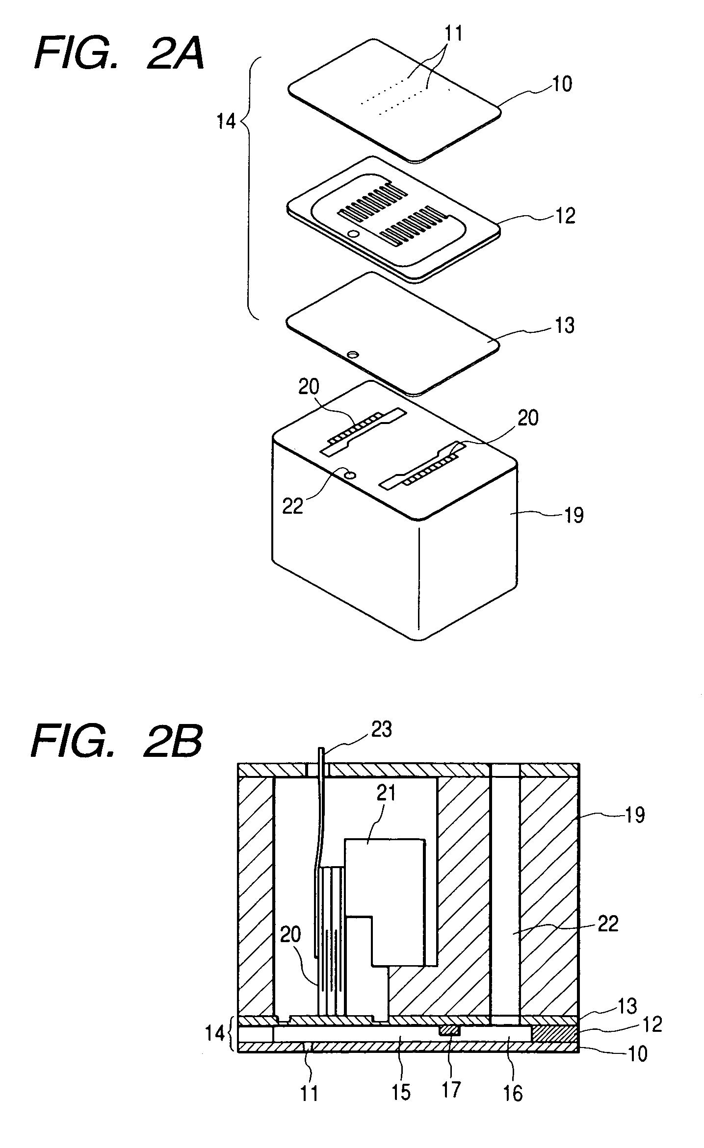
[0036]As shown in FIG. 4, the drive signal generator 31 according to the invention is configured to output, at a given cycle, a plurality of types of signals; that is, three types of signals S1, S2, and S3, for changing the amount and pattern of displacement of the piezoelectric vibrator 20 during a single jetting cycle T.

[0037]The drive signal S2 is to be applied to a piezoelectric vibrator which jets a droplet of reference volume by one single jetting operation; e.g., 10 picoliters. The drive signal S1 is to be applied to a piezoelectric vibrator of a nozzle orifice which jets a droplet of larger volume; e.g., 10.5 picoliters. The drive signal S3 is applied to a piezoelectric vibrator which jets a droplet of smaller volume; e.g., 9.5 picoliters.

[0038]The drive signal S1 is set to a drive voltage V1, and the drive signal S3 is set to a drive voltage V3, wherein the drive voltages V1 and V3 differ from a drive voltage V2 of the reference drive signal S3. As a result, the drive energ...

second embodiment

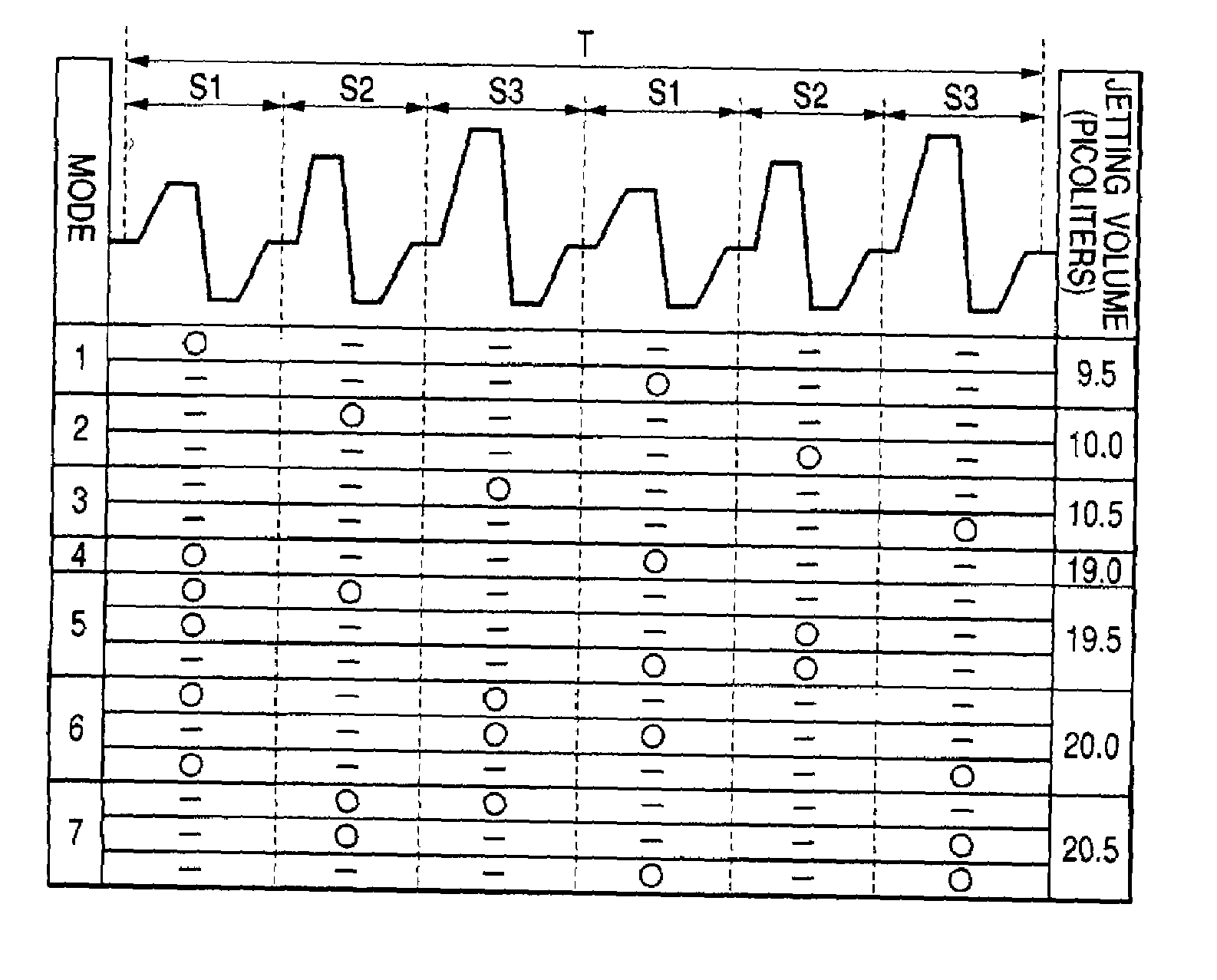
[0046]The embodiment has described a case where one droplet is jetted during one jetting cycle. As shown in FIG. 5, according to the invention, the drive signals S1, S2, and S3 are taken as a single set at frequencies which prevent occurrence of interference between meniscuses, which would otherwise be caused by a plurality of drive signals. So long as the set of drive signals is repeated several times within a single jetting cycle T, large variations in the volume of liquid between nozzle orifices can be prevented.

[0047]Namely, setting a drive signal which is capable of jetting a liquid droplet having a volume smaller than a required liquid volume as a reference drive signal, finer volume adjustment of the liquid droplet to be jetted can be attained. In the case of FIG. 5 in which the required liquid volume is 20 picoliters, since each of the reference drive signals S1 to S3 is set as a drive signal capable of jetting a liquid droplet of 0.5 picoliters, the volume adjustment of jet...

fourth embodiment

[0053]As shown in FIG. 7, a plurality of drive signals of identical drive energy; that is, four signals in the embodiment, are produced within a single jetting cycle T at a given time interval at which motion of meniscuses is not stopped by the signals, and timings at which the drive signals are to be applied to the piezoelectric vibrator 20 are selected, thereby controlling the volume of liquid.

[0054]As in the case of Mode 2, in a case where the next drive signal C2 is applied to the piezoelectric vibrator at a point in time t1 at which time T0 during which a meniscus returns to a stationary state has already elapsed since jetting of an immediately preceding droplet, a droplet K1 equal to that jetted by an immediately-preceding drive signal C1 is jetted, as shown in FIG. 8A. In contrast, as in the case of Mode 3, if the next drive signal C2 is applied to the piezoelectric vibrator at a point in time t2 at which the meniscus actuated by the immediately-preceding jetting action retu...


PUM


Abstract

A liquid jetting head includes a plurality of nozzle orifices, a plurality of pressure generation chambers associated with the nozzle orifices, and a plurality of piezoelectric vibrators for respectively varying the volume of the associated pressure generation chamber to jet a liquid droplet from the associated nozzle orifice. A drive signal generator generates a plurality of drive signals, respectively driving the piezoelectric vibrators, within a single jetting cycle of the liquid jetting head. An ID data storage stores ID data which identifies the respective nozzle orifices. A correction data storage stores correction data which corrects the amount of liquid jetted from the nozzle orifice. A drive signal supplier identifies a nozzle orifice in which the jetting amount is to be corrected, through use of the ID data, and selects at least one drive signal from the plural drive signals to adjust a displacement degree of a piezoelectric vibrator associated with the identified nozzle orifice, based on the correction data.

Description

BACKGROUND OF THE INVENTION[0001]The present invention relates to a technique for jetting a very small amount of liquid as a droplet of specified volume to a plurality of areas from nozzle orifices.[0002]An ink jet recording head capable of jetting a very small amount of liquid to a target position with relatively high accuracy is applied to a liquid jetting apparatus, such as a textile printing apparatus or a micro-dispenser.[0003]In order to improve jetting efficiency, the number of nozzle orifices is increased. The amounts of liquid jetted from nozzle orifices by one operation are subjected to a maximum variation of ±10% approximately. In order to eliminate the variations, components constituting a recording head, such as nozzle orifices, a pressure generation chamber, and a pressure generator, must be manufactured with high accuracy, which in turn results in a significant upsurge in costs of a recording head to be used for an application of this type.[0004]In order to prevent th...

Claims


Application Information

Patent Timeline
IPC IPC(8): B41J29/38B41J2/045
CPCB41J2/04581B41J2/04593B41J2/04588B41J2202/17
Inventor KITAHARA, TSUYOSHI
Owner SEIKO EPSON CORP
Why Eureka
Try Eureka