
Electric shock gun

Inactive Publication Date: 2006-06-27
CHANG HUNG YI
View PDF15 Cites 54 Cited by
  • Summary
  • Abstract
  • Description
  • Claims
  • Application Information

AI Technical Summary

Benefits of technology

The solution enables electrode bullets to travel farther and form effective circuits without risking the user, as the capacitor charging mechanism ensures safe operation and increased reach compared to conventional systems.

Problems solved by technology

However, the pressure stored by the tanks can only send the water beams to a short distance and it will be a severe problem if the water leaks which could injury the user who holding the gun.

Method used


Image

  • Electric shock gun
  • Electric shock gun
  • Electric shock gun

Examples


Embodiment Construction

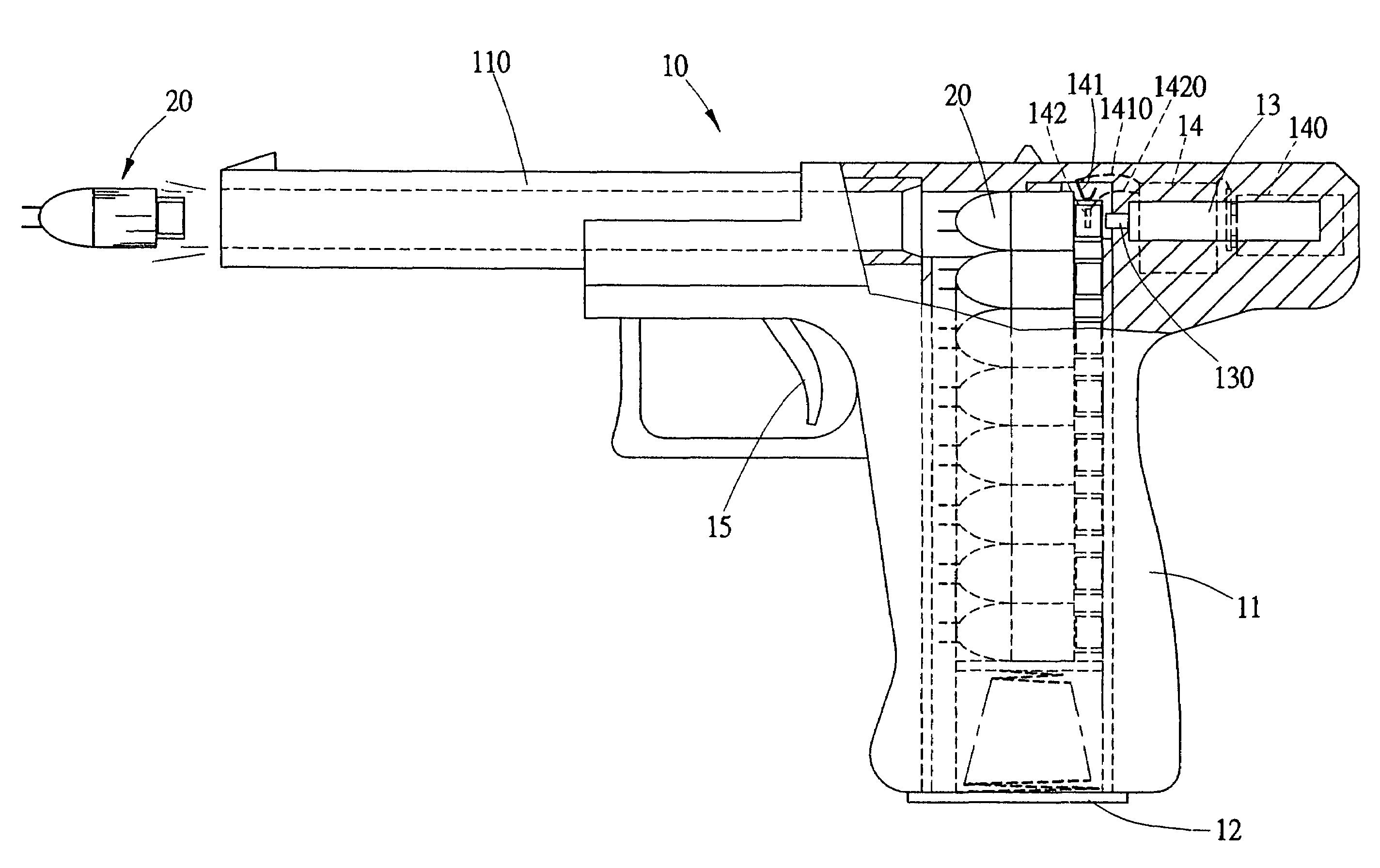
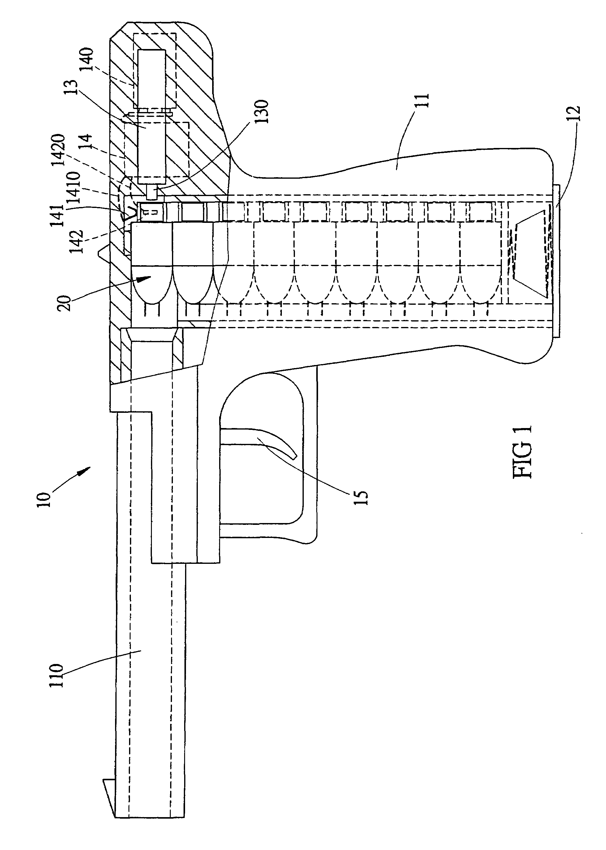
[0016]Referring to FIGS. 1 to 4, the electric shock gun in accordance with the present invention comprises a gun 10 including a barrel 110, a trigger 15 and a handle 11 in which a magazine 12 is received. A firing device 13 is received in a rear end of the gun 10 and is activated by pulling the trigger 15. The firing device 13 includes a charging device 14 and an electric power source 140 which can be a rechargeable battery or an ordinary battery.

[0017]A plurality of electrode bullets 20 are received in the magazine 12 which is removably received in the handle 11 and a biasing member is located in an inside of the magazine 12 so as to push the electrode bullets 20 toward the barrel 110.

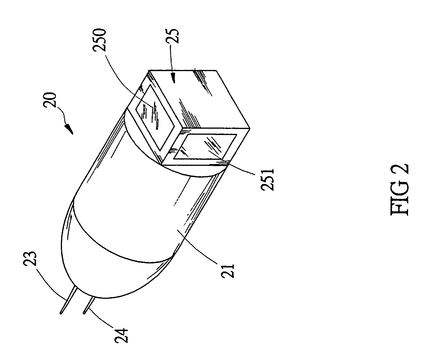
[0018]Each electrode bullet 20 includes a body 21 and a capacitor 22 is received in the body 21. The capacitor 22 includes a first board 220 and a second board 221 between which conductive agent 222 is received. Two spines 23, 24 extend from a first end of the body 21 and are connected to a positive p...


PUM


Abstract

An electric shock gun includes a barrel for receiving electrode bullets and a trigger which controls a firing device received in a rear end of the gun. The firing device includes an electric power source and a charging device. Each electrode bullet has two spines on a first end thereof and a conductive block on a second end and the firing device is electrically connected to the conductive block. Each electrode bullet includes a capacitor which is charged within a short period of time and connected to the spines and the conductive block. The electrode bullet goes out from the barrel by pulling the trigger.

Description

CROSS-REFERENCE TO RELATED APPLICATION[0001]This application is a Continuation-In-Part application of Ser. No. 10 / 202,812, filed 25 Jul. 2002 now U.S. Pat. No. 6,862,994, and entitled “ELECTRIC SHOCK GUN AND ELECTRODE BULLET.”FIELD OF THE INVENTION[0002]The present invention relates to an electric gun having a plurality of electrode bullets each have two electrodes in a form of a spine, both of which are powered by a capacitor in the bullet. The capacitor is charged within a short period of time by pulling the trigger.BACKGROUND OF THE INVENTION[0003]A conventional electric shock gun for ejecting two water beams is disclosed in FIG. 7, the gun has a pressurized tank 100 and two tanks 101 each filled with water are located in front of the pressurized tank 100. The two tanks 101 have two respective nozzles which are charged with high voltage so that when pulling the trigger 102, the two water beams are ejected out from the nozzles and may contact an animal or any conductive object and...

Claims


Application Information

Patent Timeline
Patent Type & Authority Patents(United States)
IPC IPC(8): F41A19/58F42B30/02F41C9/00F41H13/00F42B12/36H02J7/34H05C1/06
CPCF41C9/00F41H13/0031H05C1/06F42B12/36H02J7/345
Inventor CHANG, HUNG-YI
Owner CHANG HUNG YI
Learn More