Variable ratio steering system

a steering system and variable ratio technology, applied in the direction of steering initiation, instruments, vessel construction, etc., can solve the problems of increased tendency of unfavorable steering wheel offsetting, poor steering feel, and difficulty in permanent maintaining a proper relationship

Inactive Publication Date: 2006-06-20
NISSAN MOTOR CO LTD
View PDF8 Cites 13 Cited by
  • Summary
  • Abstract
  • Description
  • Claims
  • Application Information

AI Technical Summary

Benefits of technology

[0010]It is another object of the invention to provide a variable ratio steering system, which is capable of stabilizing a steering-wheel angular position, required to maintain a vehicle running state at straight ahead responsively to vehicle-speed changes, even when the proper relationship between steering wheel angle θS and road wheel steer angle θW is broken, in other words, even in presence of undesired offsetting of a steering wheel angle θS versus road wheel steer angle θW characteristic from a designed θS−θW characteristic.

Problems solved by technology

However, when a so-called tempa tire (a temporary-use tire) having a tire diameter smaller than a usual tire diameter is installed on either one of a pair of steered wheels, or when a wheel alignment difference between the steered wheels exists as a result of long driving and frictional contact with curbs, it is difficult to permanently maintain a proper relationship between a neutral position (a straight-ahead position) of the steering wheel and a position corresponding to zero average steer angle of the steered wheels.
In such a case, even during straight-ahead driving, the steering system has an increased tendency of undesired offsetting of the steering wheel from its neutral position.
Such an unstable steering-wheel angular position, which may occur depending on vehicle-speed changes during straight-ahead driving, causes a poor steering feel.

Method used


Image

  • Variable ratio steering system
  • Variable ratio steering system
  • Variable ratio steering system

Examples


first embodiment

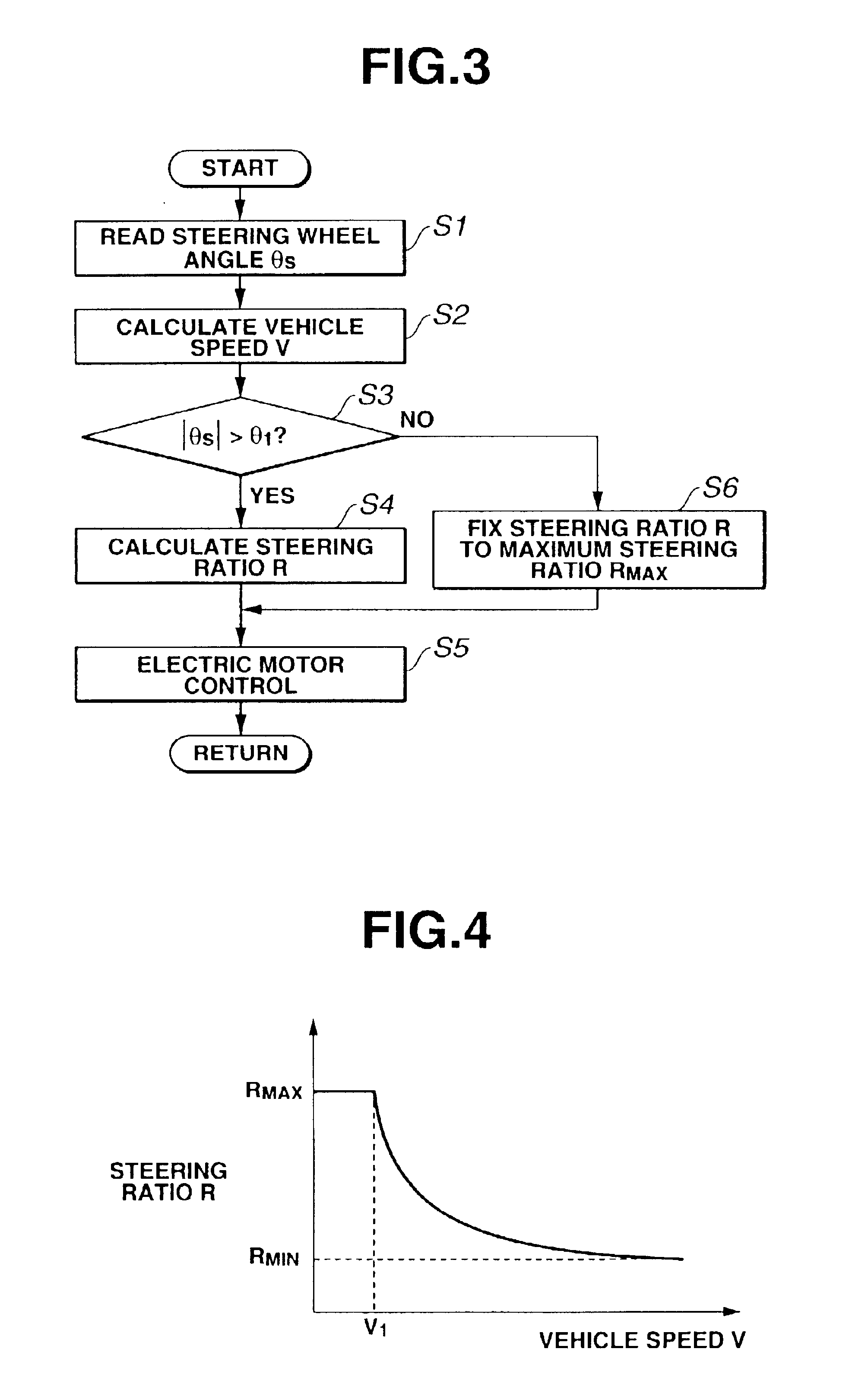
[0036]Hereinafter described in detail in reference to the flow chart shown in FIG. 3 is the variable steering ratio control routine executed by ECU 13 incorporated in the variable ratio steering system of the The arithmetic processing shown in FIG. 3 is executed as time-triggered interrupt routines to be triggered every predetermined sampling time intervals.

[0037]At step S1, steering wheel angle θS, which is detected by steering wheel angle sensor 11, is read.

[0038]At step S2, a vehicle speed V is calculated based on vehicle speed indicative signal VD from vehicle speed sensor 12.

[0039]At step S3, a check is made to determine whether an absolute value |θS| of steering wheel angle θS, read at step S1, exceeds a predetermined angle θ1. In the shown embodiment, predetermined angle θ1 is set to a predetermined low angle, such as 15 degrees or less, substantially corresponding to a neutral position (θS=0) of steering wheel 1. When the answer to step S3 is in the affirmative (YES), that ...

second embodiment

[0046]According to the system of the second embodiment shown in FIGS. 6 and 7, when the answer to step S3 is in the negative (NO), that is, in case of |θS|≦θ1, ECU 13 determines that the vehicle is maintained in a substantially straight-ahead driving state. In this case, the routine returns from step S3 to step S1, so as to bring variable steering ratio mechanism 3 into a non-control state. In the variable steering ratio control routine shown in FIG. 7, the processing of step S1 and steering wheel angle sensor 11 serve as a steering wheel angle detector (steering wheel angle detecting means) that monitors or detects steering wheel angle θS. The processing of step S2 and vehicle speed sensor 12 serve as a vehicle speed detector that monitors or detects vehicle speed V. The procedures of steps S3, S4, and S5 serve as a steering ratio control circuitry (steering ratio control means).

[0047]With the previously-discussed arrangement of the second embodiment, suppose that the vehicle is ma...

third embodiment

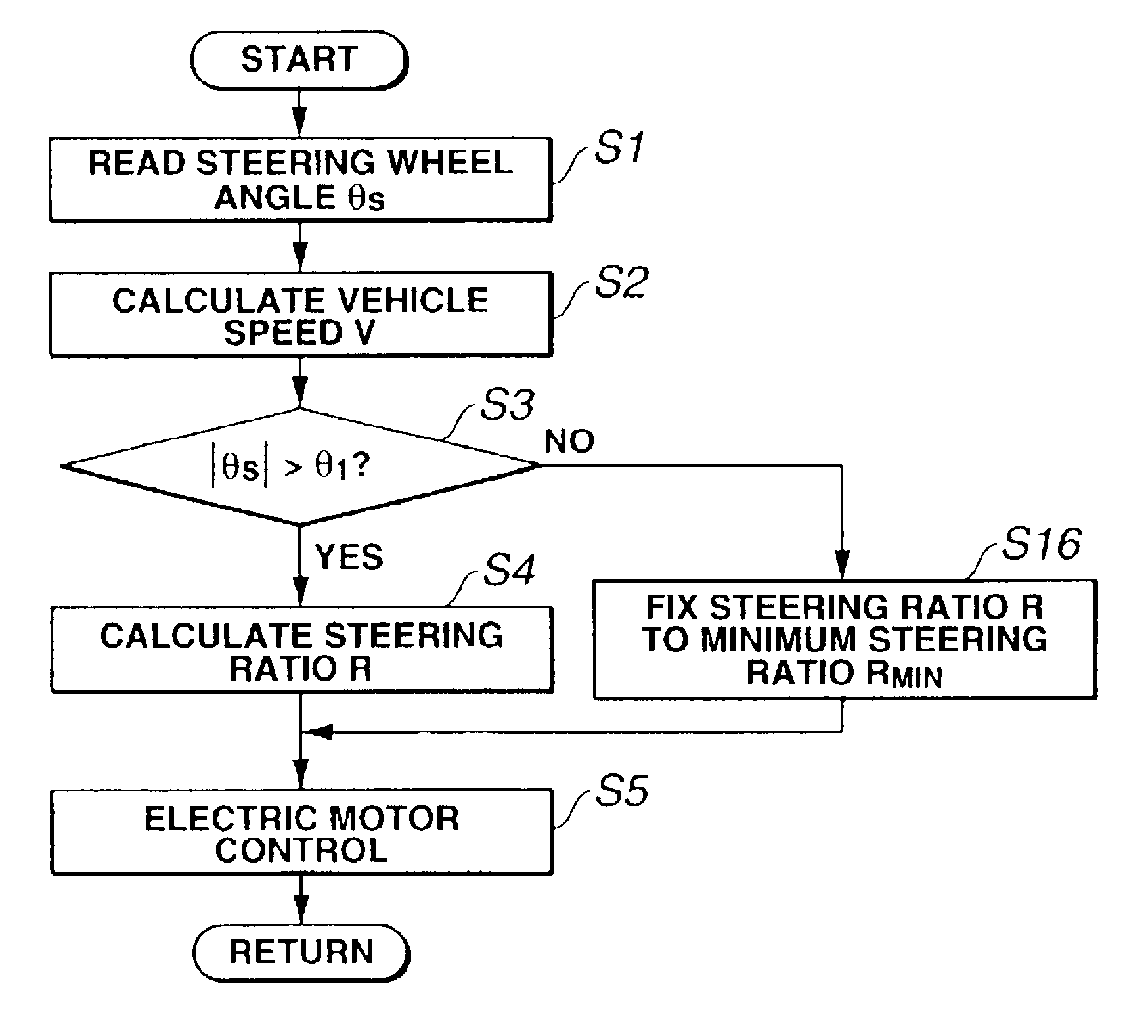
[0049]According to the system of the third embodiment shown in FIGS. 8 and 9, when the answer to step S3 is in the negative (NO), that is, in case of |θS|≦θ1, ECU 13 determines that the vehicle is maintained in a substantially straight-ahead driving state. In this case, the routine proceeds from step S3 to step S16. At step S16, in order to prevent or inhibit steering ratio R from fluctuating or changing depending on changes in vehicle speed V, steering ratio R is controlled or fixed to predetermined minimum steering ratio RMIN suited to the high speed range. In other words, in case of |θS|≦θ1, predetermined minimum steering ratio RMIN suited to the high speed range is held or determined as steering ratio R, until steering wheel angle θS exceeds predetermined angle θ1. Thereafter, the routine proceeds from step S16 to step S5. At step S5, first, steering ratio controlled variable C is calculated based on both a sign of steering wheel angle θS and predetermined minimum steering ratio...


PUM


Abstract

In a variable ratio steering system of a vehicle with a variable steering ratio mechanism varying a steering ratio R of steering wheel angle θS to road wheel steer angle θW at steered road wheels, a vehicle speed sensor, and a steering angle sensor, a steering ratio control unit controls the steering ratio according to a fixed steering ratio characteristic when the steering wheel angle θS is less than or equal to a predetermined angle θ1 substantially corresponding to a neutral position of a steering wheel. Conversely when the steering wheel angle θS is greater than the predetermined angle θ1 substantially corresponding to the neutral position of the steering wheel, the steering ratio control unit controls the steering ratio according to a vehicle-speed dependent steering ratio characteristic that a steering angle versus road wheel steer angle characteristic varies depending on a vehicle speed value.

Description

TECHNICAL FIELD[0001]The present invention relates to a variable ratio steering system capable of varying a steering ratio of steering wheel rotation angle to steer angle at steered road wheels.BACKGROUND ART[0002]Many steering systems provide variable ratio steering. Such variable ratio steering systems have been disclosed in Japanese Patent Provisional Publication No. 4-159178 (hereinafter is referred to as “JP4-159178” and corresponding to U.S. Pat. No. 5,265,019) and Japanese Patent Provisional Publication No. 7-257406 (hereinafter is referred to as “JP7-257406” and corresponding to U.S. Pat. No. 5,489,004).[0003]The variable ratio steering system disclosed in JP4-159178 includes a transmission ratio changing mechanism arranged between a steering wheel and tie-rod linkages, an actuator driving the transmission ratio changing mechanism, steering sensor means, a vehicle speed sensor, and a controller. The transmission ratio changing mechanism serves to change a transmission ratio ...

Claims


Application Information

Patent Timeline
Patent Type & Authority Patents(United States)
IPC IPC(8): B62D6/00B62D5/00B62D5/04B62D5/22B62D6/02B62D101/00B62D113/00
CPCB62D6/02B62D5/008B62D6/00
Inventor HARA, KAZUO
Owner NISSAN MOTOR CO LTD
Why Eureka
Try Eureka