
Methods and apparatus for operating production facilities

a production facility and equipment technology, applied in the direction of process and machine control, nuclear elements, electric devices, etc., can solve the problems of labor intensive testing, inefficient system operation, and only reliable test results and assumptions underlying efficiency calculations

Active Publication Date: 2006-06-20
GENERAL ELECTRIC CO
View PDF18 Cites 10 Cited by
  • Summary
  • Abstract
  • Description
  • Claims
  • Application Information

AI Technical Summary

Benefits of technology

[0007]In another aspect, a production system for producing an output is provided. The system includes at least one production facility that includes a first resource receiving system, and a second resource configured to control and util

Problems solved by technology

However, due to the periodic scheduling of efficiency testing, the validity of the testing results and the assumptions underlying the efficiency calculations may only be reliable for a short time period until the tests are run again.
For example, various causes of uncertainty may undesirably introduce misleading data into calculations relied upon to achieve optimal production system dispatch, which as a result may produce inefficient system operations.
Testing components and testing the facility at shortened intervals may improve economic dispatch curves, but testing is labor intensive may require operational limits on the facility during the time period the testing is taking place.

Method used


Image

  • Methods and apparatus for operating production facilities
  • Methods and apparatus for operating production facilities
  • Methods and apparatus for operating production facilities

Examples


Embodiment Construction

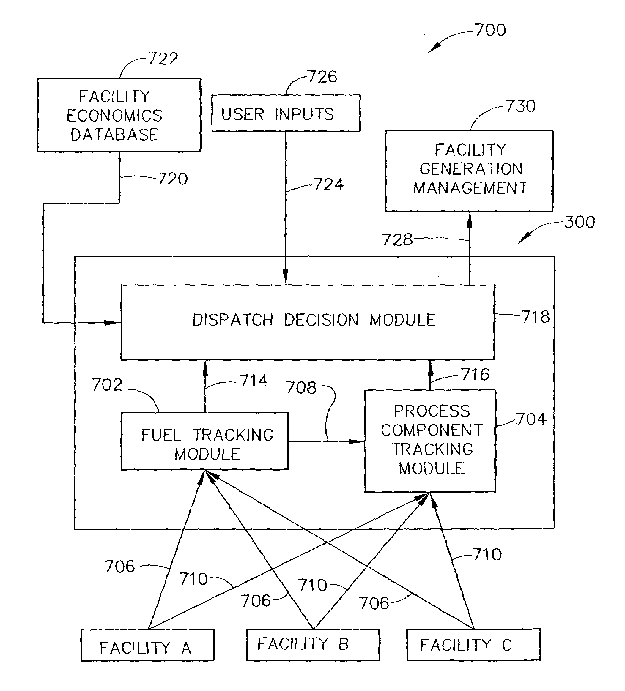
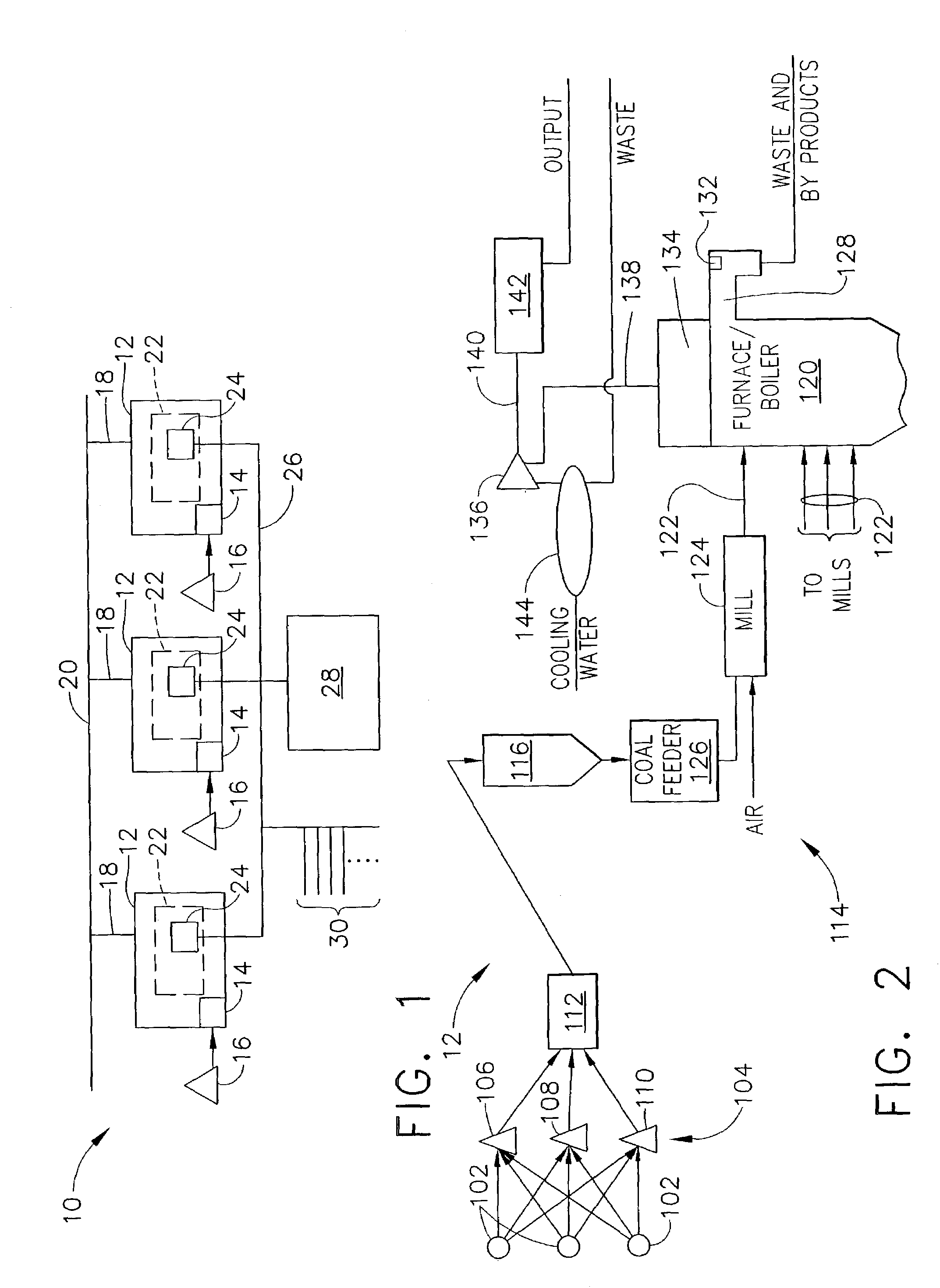
[0016]FIG. 1 is a schematic diagram of an exemplary production system 10 that includes at least one production facility 12 that includes a receiving system 14 for supplying a first resource 16, such as coal, to facility 12. In the exemplary embodiment, facility 12 is a coal-fired power generation plant that receives coals from a plurality of sources. Each facility 12 may have different operating characteristics from each other facility 12, including, but not limited to, facility production capability, efficiency, and availability. Each facility 12 also includes a production output 18 that is coupled to a transmission system 20. In the exemplary embodiment, outputs 18 are transmission wires that connect each facility 12 a transmission system, or grid 20. In an alternative embodiment, output 18 may be a pipeline for transporting liquid or gaseous produced goods. In another alternative embodiment, each output 18 may be a transport system for transporting discrete produced goods through...


PUM


Abstract

A method and apparatus for operating a production system that includes a plurality of production facilities is provided. The method includes receiving, in real-time, for each facility, cost data for a first resource used by each respective facility to produce an output, receiving, in real-time, for each facility, cost data for a second resource used by each respective facility to produce the output, determining, in real-time; an automated incremental cost curve for the system based on a level of production of each facility and the received resource cost data, and determining a production output target for each production facility to achieve an optimum production system output based on the real-time incremental cost curves. The system includes at least one production facility that includes a software code segment programmed to determine, in real-time, an incremental cost of a first resource based on a level of production of each respective facility.

Description

BACKGROUND OF THE INVENTION[0001]This invention relates generally to the control of production facilities, and more particularly to a system for optimizing the output of a system of production facilities.[0002]At least some known production systems include a plurality of production facilities that operate in parallel such that each facility receives production resources independently of the other facilities in the system. The output of such production facilities may be linked via a common stream of commerce. For example, an electric utility may have a plurality of independent generating facilities located throughout a territory. Each generating facility may receive fuel from independent suppliers and the output of each facility may be coupled through a common transmission system or grid, such that, if one facility became unable to deliver a required output to the grid, another facility should be able to increase its output to accommodate for the shortfall. This process is nearly tra...

Claims


Application Information

Patent Timeline
IPC IPC(8): G05B13/02G06Q10/06G06Q30/02
CPCG06Q30/0283G06Q10/06
Inventor ROGERS, PAUL MATTHEWMAXSON, JAMES ANDREWCELMINS, ILGA
Owner GENERAL ELECTRIC CO
Learn More