Method and device for ride height control of a motor vehicle
- Summary
- Abstract
- Description
- Claims
- Application Information
AI Technical Summary
Benefits of technology
Problems solved by technology
Method used
Image
Examples
Embodiment Construction
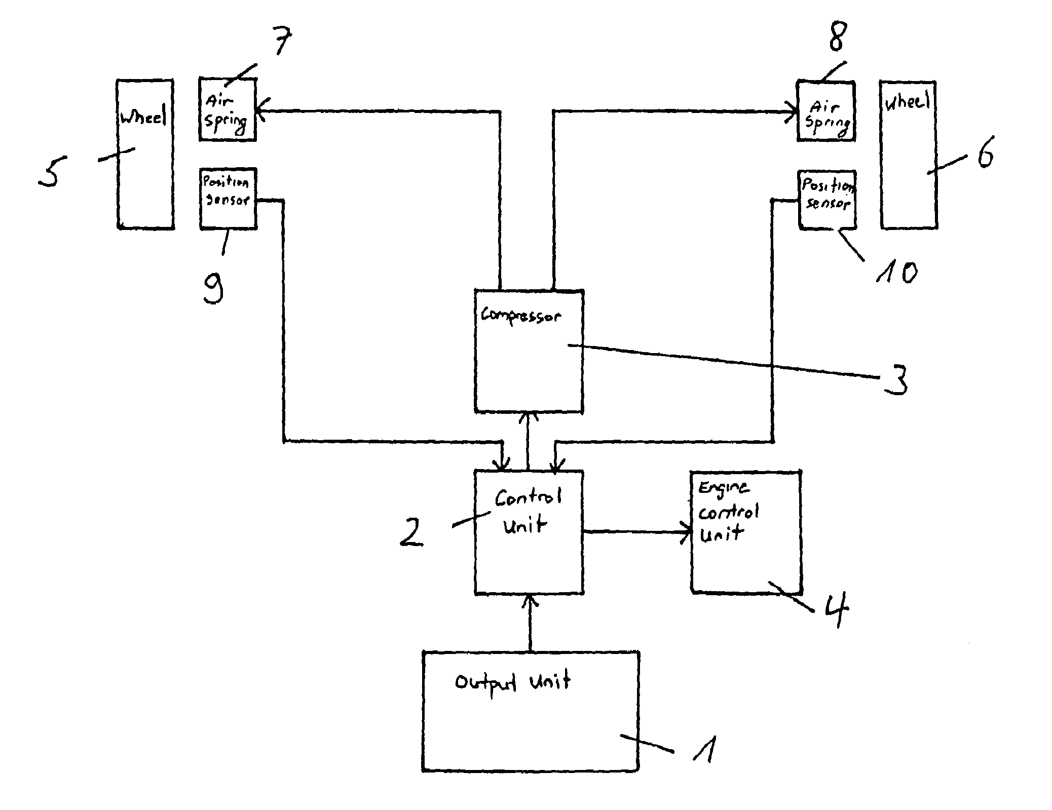
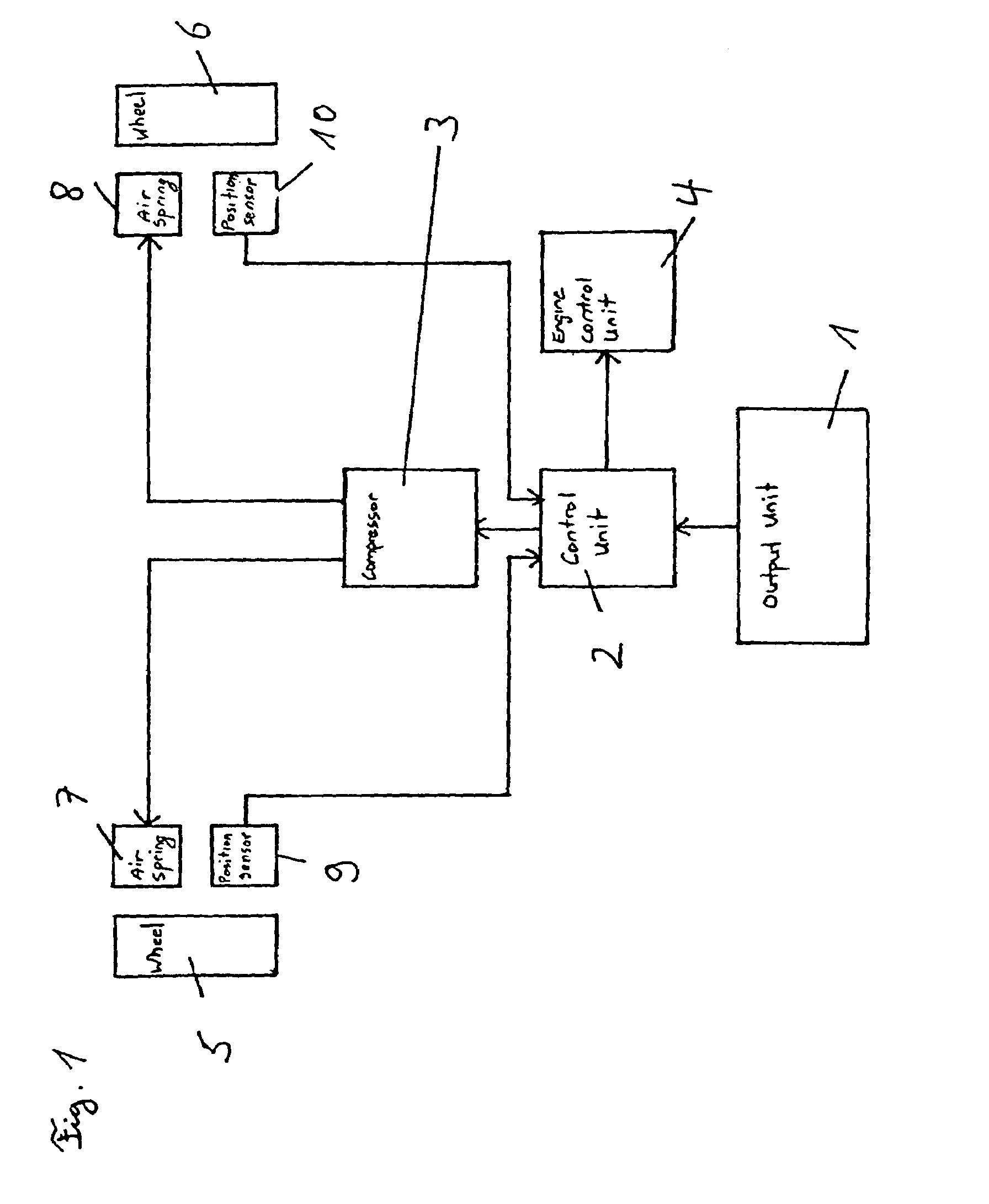
[0018]The device for automatic ride height control includes an input and output unit 1, a control unit 2, a compressor 3, an engine control unit 4, the vehicle wheels 5, 6 having associated air springs 7, 8, and position sensors 9, 10 associated with vehicle wheels 5, 6.
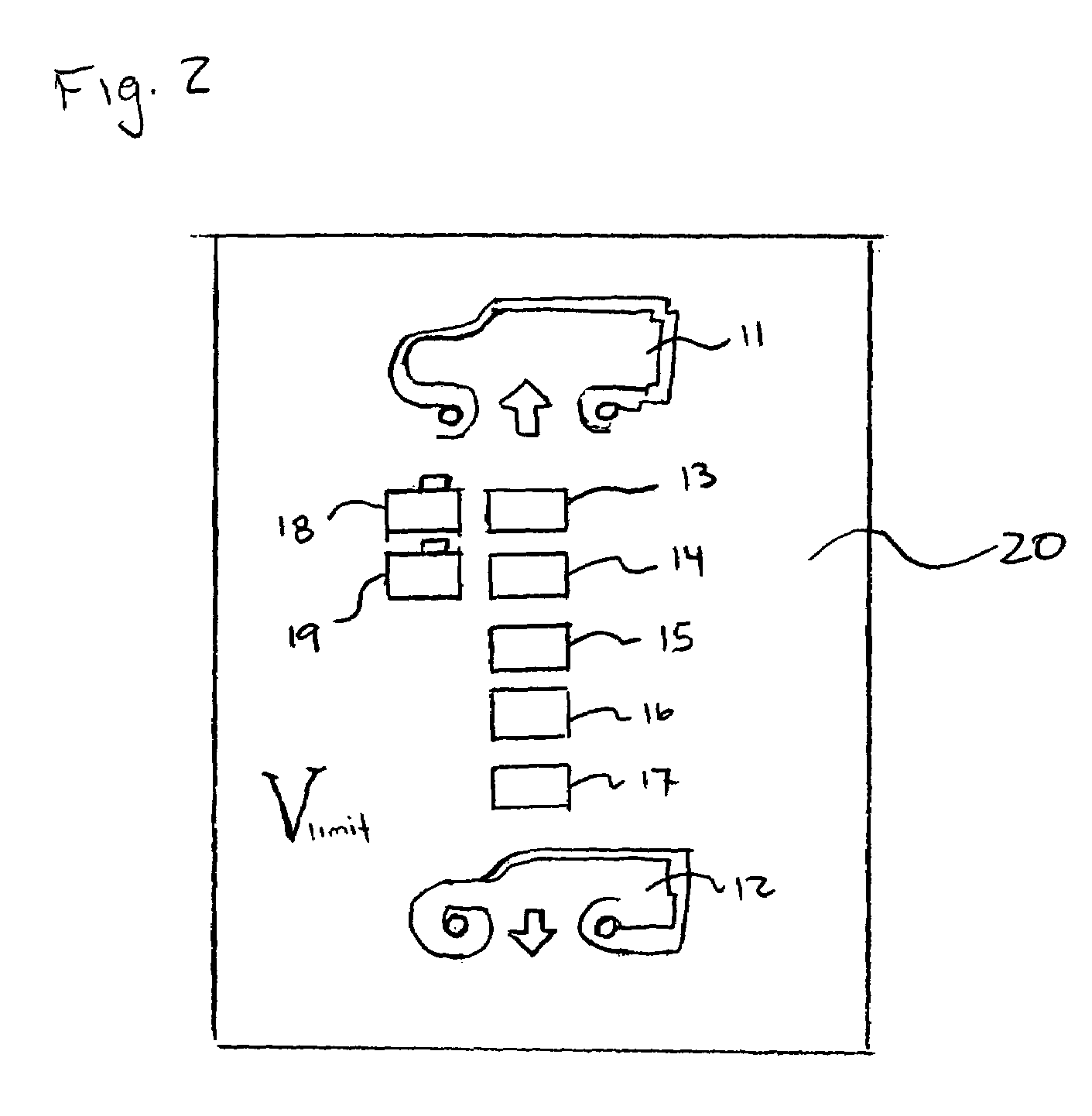
[0019]The driver is able to set and possibly fix a desired setpoint level position via input and output unit 1, which will be explained in greater detail below. In addition, the driver may have the set level position displayed to himself. The set setpoint level position is transmitted to control unit 2 via input and output unit 1. Control unit 2 ascertains from the data of position sensors 9, 10 the actual level position and activates compressor 3 accordingly, which inflates air springs 7, 8 accordingly or is caused to inflate them, so that the desired setpoint level position is reached. In order to give the driver the possibility of loading compressor 3 less strongly or to rely situationally on a certain ground clea...
PUM
 Abstract
Description
Claims
Application Information
 - R&D
- Intellectual Property
- Life Sciences
- Materials
- Tech Scout
- Unparalleled Data Quality
- Higher Quality Content
- 60% Fewer Hallucinations
Browse by: Latest US Patents, China's latest patents, Technical Efficacy Thesaurus, Application Domain, Technology Topic, Popular Technical Reports.
© 2025 PatSnap. All rights reserved.Legal|Privacy policy|Modern Slavery Act Transparency Statement|Sitemap|About US| Contact US: help@patsnap.com


