
Heat engine

a heat engine and engine body technology, applied in the field of heat engines, can solve the problems of insufficient supply of drinking water and water for irrigation, lack of infrastructure, and inability to provide electrical grid, and achieve the effect of improving efficiency

Inactive Publication Date: 2006-06-20
OHIO STATE INNOVATION FOUND
View PDF16 Cites 90 Cited by
  • Summary
  • Abstract
  • Description
  • Claims
  • Application Information

AI Technical Summary

Benefits of technology

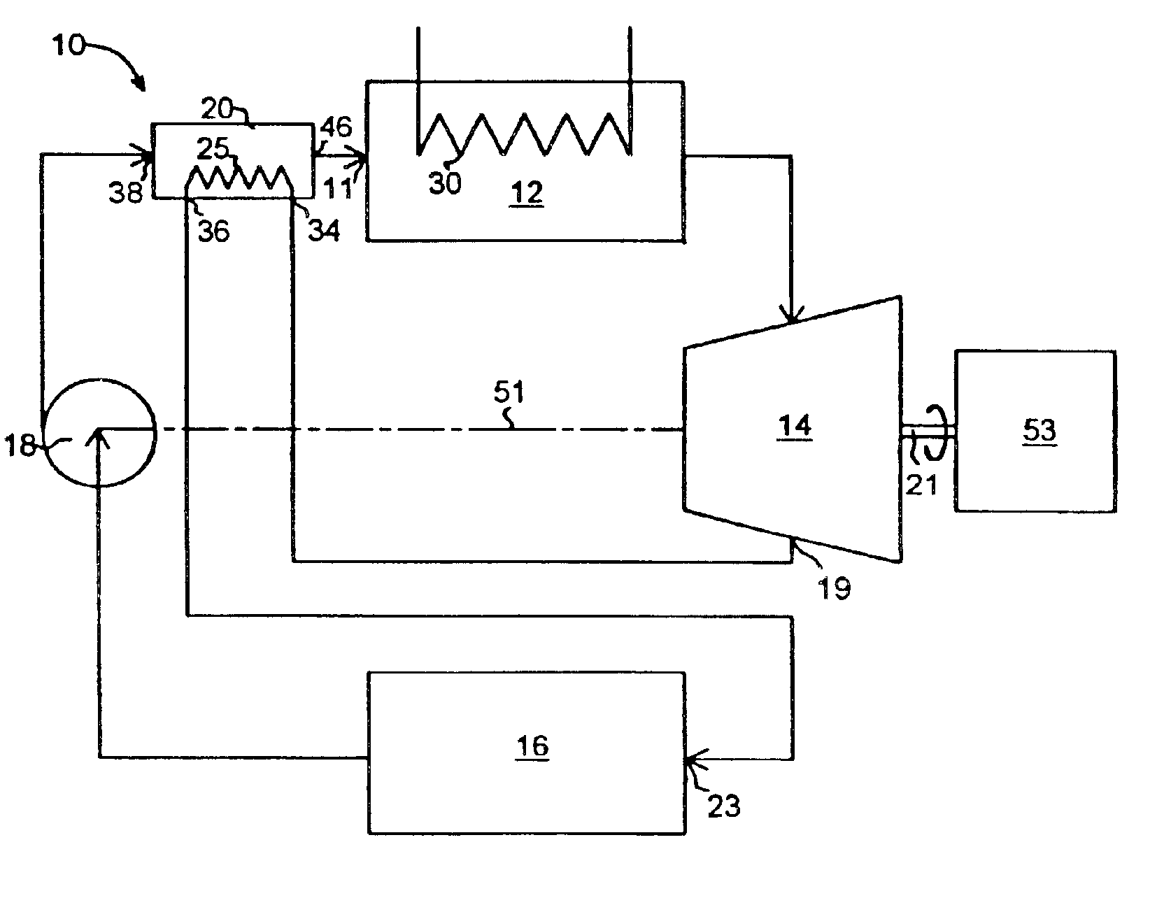
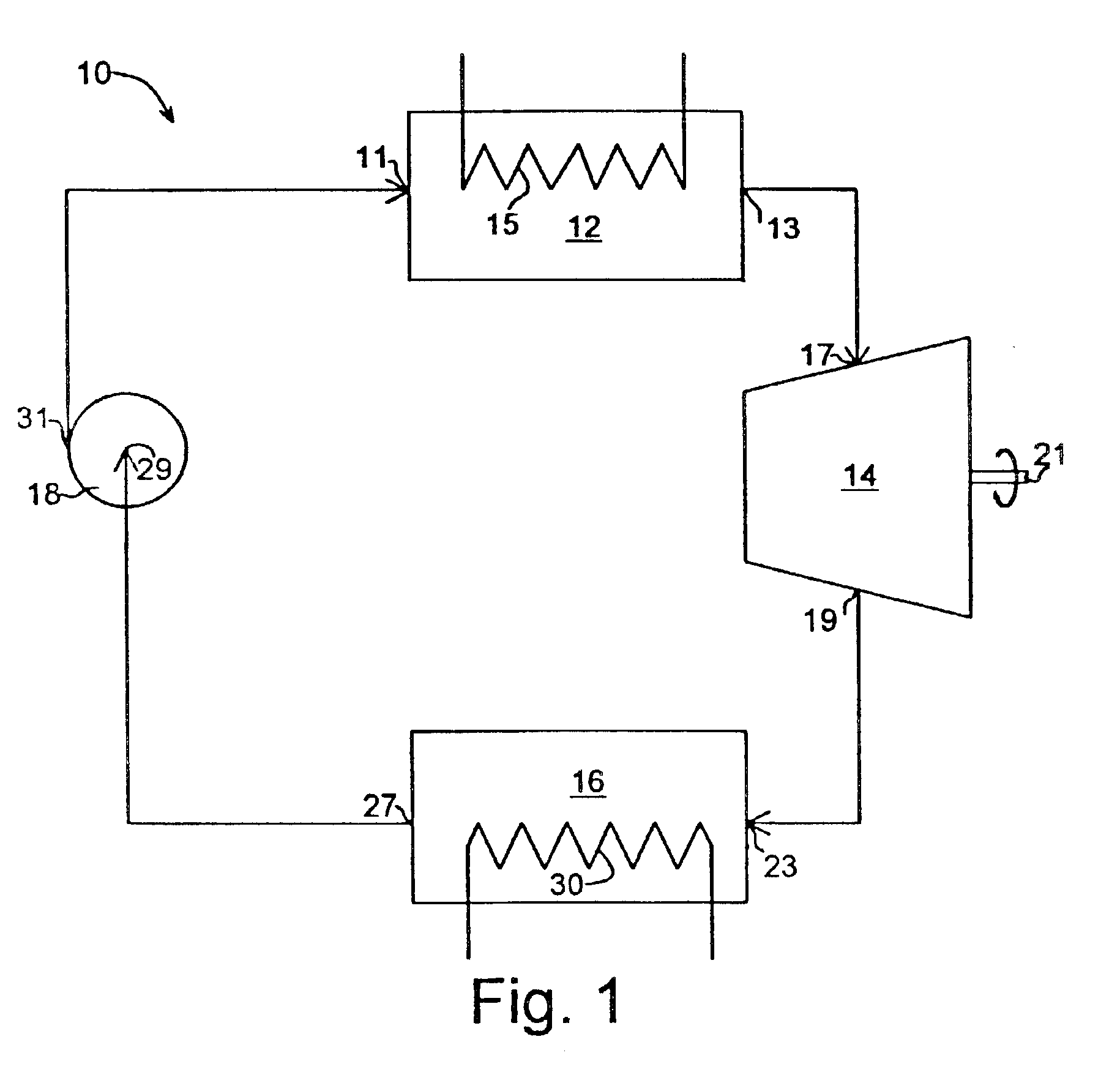
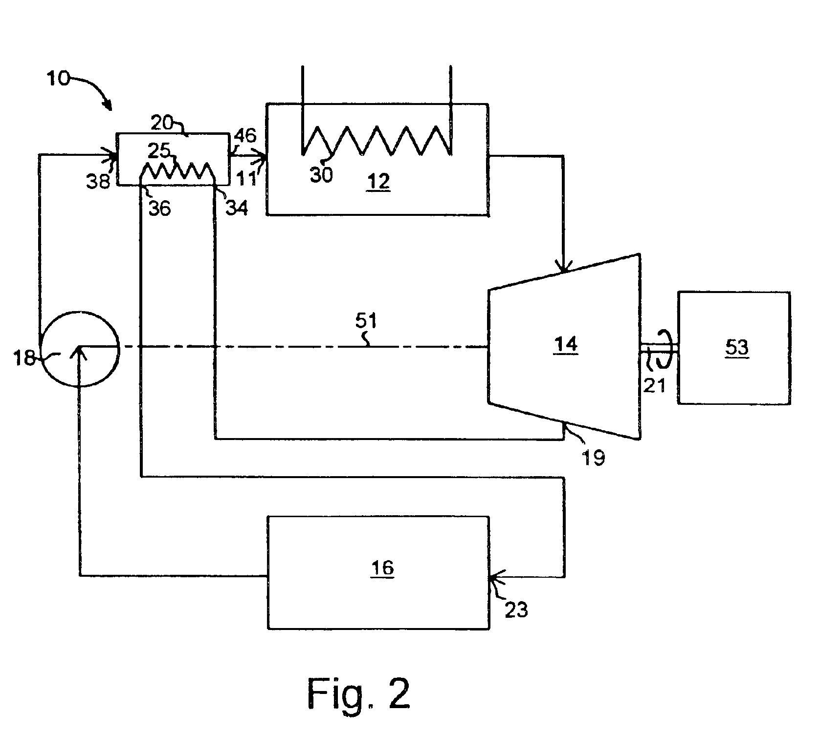
[0034]A heat engine operating with a low boiling working fluid and a positive displacement rotating expander such as a gerotor or scroll obtains improved efficiencies using superheated working fluid to preheat the fluid prior to entering the boiler or use of cool working fluid to cool systems pumps and the expander. The heat engine is combined with a variety of absorption and compression heat transfer devices to use low temperature heat sources such as solar, bio-mass, and waste heat to provide refrigeration, and heating, work output including pumping and heating of subterranean water and electrical generation.

Problems solved by technology

In most of the developing third world, adequate supplies of drinking water and water for irrigation are a scarce commodity.
These locations generally do not have the infrastructure to provide an electrical grid to pump the water with electricity nor do they have the infrastructure to provide roads to bring in electrical generators or even the fuel for those generators.
Therefore without an electrical grid, or without generators to generate electricity, isolated areas do not have potable water nor do they have the refrigeration to keep medicine or foodstuffs from spoiling.
Here the lack of cooling capabilities severely limits the production of various products.
Because of the lack of cooling, milk production is limited to Grade B.

Method used


Image

  • Heat engine
  • Heat engine
  • Heat engine

Examples


embodiment 800

[0185]The vertical space 806b of generator 800 contains an exhaust distributor 822 attached to the interior wall of vertical section cylinder 844b for improved heat transfer from the combustion products 826 to the working solution contained first fluid space 802b. In effect, embodiment 800 of FIG. 39 has gas fired into horizontal cylinder section 844a with a vertical shell (first fluid space) 802b and tube 846 tube extension. The LiBr-water working solution flows in the annulus 802a around the central fired cylinder 844a. The central horizontal cylinder 844a has helical fins 848 about its exterior surface with the circulating heating fluid 830 flowing in tube 846 wound between the helical fins 848. Circulating fluid 830 also flows in the interior of helical tube 846 within the annulus (first fluid space) 802b around the vertically fired cylinder 844b. As illustrated, the hot heating fluid 830 enters the vertical portion of the vertical fluid space 804b via inlet 808, flows downward ...

embodiment 900

[0186]Embodiment 900 shown in FIG. 40 consists of a cylindrical space in which the working solution 932 flows and which has two sets of vertical tubes, one set 946 for a heating fluid such as a solar fluid and a second set 944 for a second heating fluid such as hot combustion products 926. A separator 916 allows for separation of the two-phase working solution 932 into the refrigerant vapor component and the weak working solution (absorbent) 920.

[0187]The generator 900 has a cylindrical first fluid space 902 formed in the interior of cylinder 942, a second fluid space 904 in heat exchange relation with first fluid space 902 with the second fluid space 904 being an interior tubular space formed by a plurality of tubular vertical members 946 opening to an upper manifold 956 with an inlet 908 and a lower manifold 958 with an outlet 910, and a third fluid space 906 in heat exchange relation with first fluid space 902 and being the interior tubular space formed from by a plurality of tub...


PUM


Abstract

A heat engine (10) achieves operational efficiencies by: 1) recovering waste heat from heat engine expander (14) to preheat heat-engine working fluid, 2) using super-heated working fluid from compressor (402) to pre-heat heat-engine working fluid, and 3) using reject heat from condenser (93) and absorber (95) to heat the heat-engine boiler (12). A dual heat-exchange generator (72) affords continuous operation by using gas-fired heat exchanger (212) to heat generator (72) when intermittent heat source (40), e.g., solar, is incapable of heating generator (72). The combination of heat engine (10) and absorption and compression heat transfer devices (60, 410) allows use of low-temperature heat sources such as solar, bio-mass, and waste heat to provide refrigeration, heating, work output including pumping and heating of subterranean water and electrical generation.

Description

CROSS REFERENCE TO RELATED APPLICATIONS[0001]This application is the United States national stage of and claims the benefit of PCT Application PCT / US00 / 34015 filed on Dec. 15, 2000 (published as WO 01 / 44658 on Jun. 21, 2001) which claims the benefit of U.S. Provisional Application 60 / 172,188 filed on Dec. 17, 1999 and U.S. Provisional Application 60 / 243,164 filed on Oct. 25, 2000 all of which are incorporated by reference as if completely written herein.BACKGROUND OF THE INVENTION[0002]1. Field of the Invention[0003]This invention pertains to heat engines more particularly to the use of heat engines in combination with various low energy heat sources and cooling and / or heating absorption and compression cycles and the use of heat engine working fluid to preheat a boiler and capture frictional and other heat loss from an expander and other pumps in the system.[0004]2. Background of the Invention[0005]In most of the developing third world, adequate supplies of drinking water and water...

Claims


Application Information

Patent Timeline
Patent Type & Authority Patents(United States)
IPC IPC(8): F01K25/08F02C1/05F02C6/18F25B6/04F25B15/00F25B15/02F25B15/04F25B15/06F25B27/00F25B27/02F25B33/00F28F1/08F28F9/22
CPCF01K25/08F02C6/18F25B15/008F25B15/02F25B27/00F25B33/00F28F1/08F28F9/22F02C1/05Y02E50/11F25B6/04F25B15/04F25B15/06F25B27/02F25B2315/002F25B2333/003Y02B30/625Y02A30/274Y02E50/10
Inventor CHRISTENSEN, RICHARD N.CAO, JIMINGHENKEL, E. THOMAS
Owner OHIO STATE INNOVATION FOUND
Learn More